
Last Updated on 05 August 2016 by
Transverse stability is the ability of a vessel to resist and recover from heeling over. It important in the sense that this is what prevents a vessel rolling over and capsizing. For sailing vessels, stability is also needed to develop power under sail other than downwind.
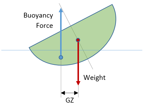
Stability is a force moment, i.e. forces separated by a distance trying to cause rotation. These forces are the weight of the vessel and the buoyancy of the hull. When a hull heels, the buoyancy force tracks the centre of the immersed volume of the hull and moves. The weight of the vessel acts from the centre of gravity and remains fixed.
When the separation distance between the forces reduces to zero, there is no moment any more and an equilibrium is reached.
The way the separation distance between weight and buoyancy evolves with heel fully determines the stability behaviour of a craft in flat water. This distance is often referred to as GZ. The greater the GZ distance, the more effective the forces become.
It is useful to look at stability and the GZ distance as a combination of two distinct contributions: form (or shape) stability and weight stability, or more accurately the impact of the height of the centre of gravity of the vessel.
Form Stability
As its name suggests it, form stability is the component that depends on hull shape. When wider, flatter sections are heeled, the centre of the immersed volume of the hull shifts away from the craft centreline quite significantly. This centre is referred to as centre of buoyancy and – by definition – is always some distance below the waterline.
This effect is nowhere near as prevalent for deeper hulls, hulls with rounded sections or slack bilges. Here below, rather than falling into improbable extremes to make a point, I have drawn two reasonable hull sections. The heavier boat would make a very acceptable medium displacement yacht or commercial vessel. The light boat is a little short on freeboard for the purpose of the demonstration that follows later.
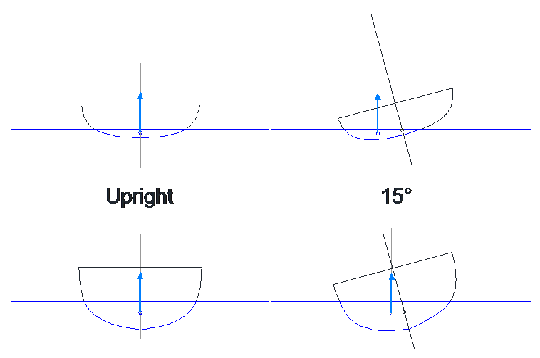
For the same heel angle, the centre of buoyancy of the shallower hull moves aside about twice as much: this is form stability.
Form stability prevails at low to moderate angles of heel and declines rapidly as heel becomes significant. Eventually, it can become the main contributor towards inverted stability, as we will see shortly.
Weight Stability
Weight stability, on the other hand, is the contribution afforded by the centre of gravity achieved in the vessel. The fore-and-aft position of the centre of gravity impacts trim, which is a different matter; its transverse location must be on the centreline of the boat, otherwise the vessel would have a permanent list. The only degree of freedom left is vertical: the height of the centre of gravity, or vertical centre of gravity usually referred to as VCG.
While this often come as unexpected at first, nearly all vessels afloat have their centre of gravity located above the centre of buoyancy. This condition favours the development of two stable equilibrium points: upright and capsized.
Now, from a seaman’s point of view, we can’t do anything about form stability short of building another boat. What is important is understanding the impact of changing the height of the centre of gravity through loading or altering the vessel, in relation with the shape of the hull.
Restarting with the same two hulls used above, we can draw the stable range of heights for the centre of gravity in green, and the unstable one in red. Each time, the stability limit is reached when the centre of gravity crosses “over and above” the centre of buoyancy.
The safe range for the VCG changes quite dramatically with heel and depends a lot on hull shape:
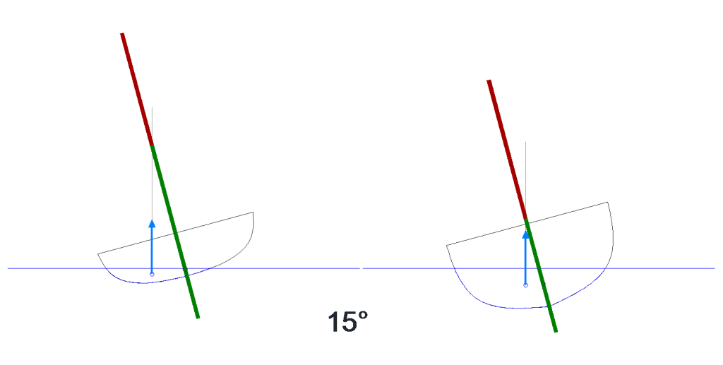
At 15° heel, the flatter, shallower hull tolerates being loaded high a lot better than the deeper, fuller one on the right. Even loaded up quite high above deck level, it will still feel safe due to the large margin existing upwards on the green line.

However, if a knock-down or heavy roll to 80° heel is a possibility, the shallow hull loses its edge completely when it comes to carrying weight up high. Note also how a higher freeboard would help. It would now require a ballasted keel to come back, while the boat on the right might still get away with a short keel or internal ballast.
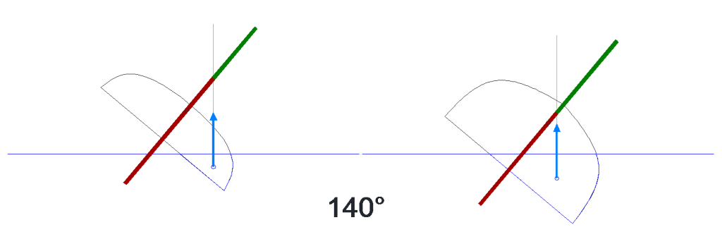
If we now invert the boats to 140°, trying to keep them self-righting becomes extremely challenging. Even the deep hull would require a very deep ballasted keel to come back.
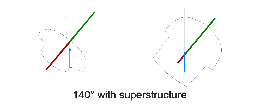
So far, our boats had flat decks and things started going wrong when the deck got into the water, so let’s add some superstructure on them: the improvement is very significant. On the right, a fishing vessel with a large wheelhouse would still be self-righting at 140° heel in most cases.
Generally speaking, designing ocean-going motor vessels that are fully self-righting is not too onerous; sufficient volume in a relatively low and long superstructure with a cambered roof normally goes a long way towards rendering them unstable when inverted.
Designing fully self-righting sailing yachts is extremely constraining on the other hand and not normally attempted. The drawbacks incurred exceed by far the hypothetical advantage of recovering from a capsize. This said, the development of canting keels has opened up new avenues for those designs and, following a spate of rescues from inverted racers off South Africa in the 1990s, some racing rules do now require vessels to be able to re-right themselves.
Canting keels do go a long way in this direction, but prior to this, some Open 60s featured sealed, watertight mast sections and lateral water ballast compartment can be used to achieve the loss of inverted stability described here.
Implications
As shown above, when it comes to overall stability, it is not so much a matter of how flat the hull is or is not, but more a question of beam at the waterline and hull depth. A deep hull with a firm turn of the bilge as depicted is still relatively “flat bottomed”, but this still doesn’t make it anywhere near as stable initially as the shallow hull.
Practically, stability should come from a combination of form stability at small angles, where the vessel operates most of the time, and weight stability at high and abnormal angles for safety. This is true for motor vessels as well as sailing yachts.
The old English racing cutters, such as Alain Gerbault’s Firecrest in the 1920s, or some more recent ULDBs are examples of very narrow yachts that rely on weight stability almost exclusively. Some of the Whitbread maxis of the 1980s featured very rounded sections and also significantly relied on weight stability. All of them sailed at rather atrocious heel angles – and this wasn’t their only flaw.
Ballasted sailing yachts do not normally see variations in loading as large as fishing vessels for example and, as they need reserve stability to resist heeling forces while sailing, they don’t normally get into trouble due to lack of static stability alone either. Dynamic considerations must be taken into account.
I only ever came across one example of a yacht that had developed truly severe static stability issues. After a decade-long refit-and-improvement programme on the hardstand, it was re-launched so top-heavy that it soon blew over and stayed heeled near 90° for 3 days, until the wind dropped completely.
Righting Moment
Stability was discussed so far in relative terms. How stiff a vessel really is when confronted to external forces trying to heel it relates to righting moment.
The righting moment is the product of the righting arm GZ and vessel weight; for convenience, it is often expressed in kilogram-metres or foot-pounds, even though technically mass and weight shouldn’t be confused this way and we should deal in Newton-metres.
Righting Moment = GZ x Vessel Weight
Beamy and relatively shallow hulls exhibit significant form stability at small angles and tend to develop higher peak GZ values earlier; heavy vessels are usually too deep in relation with their beam to be able to produce comparable GZ figures, but they offset this with their displacement:
Larger GZ x Smaller Displacement ≈ Smaller GZ x Larger Displacement
In practice, displacement takes over at some point and heavy vessels achieve higher righting moments and stability than lighter ones of the same length. They also tend to achieve their maximum stability at greater angles, but deep bulb keels on light boats can offset this aspect completely.
In the case of sailing yachts, seeing righting moment increasing with displacement is just as well, because heavier vessels require more power to offset their displacement. If we redraw the example used earlier, but now with the weight and buoyancy forces reflecting the difference in displacement between the vessels, we obtain:
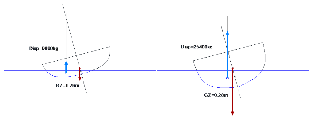
Righting moment: the vessel on the left develops a much better righting arm GZ, but has less than a quarter of the displacement of the heavy hull.
Calculating the righting moments, the light vessel offers 0.76 x 6000 = 4560kg-m, while the heavy one gives 0.28 x 25400 = 7112kg-m; this represents 56% more as a result. Will it make the boat harder to capsize? On the paper certainly, but at sea nothing is not that simple: Parts 3, 4 and 5 of this series discuss dynamic stability considerations for sailing and motor vessels.
Stability Versus Boat Size
Stability, in absolute terms, is determined by the GZ distance multiplied by the weight of the craft. So, what happens if the length of the craft is doubled?
At a first glance, one would assume that all dimensions of the vessel would simply double: the volume of the hull would scale up by a factor 2 in three different direction (length, beam and depth), so displacement would increase by 2 x 2 x 2 = 8 times.
Since GZ is a transverse distance, one would also expect this to scale up by two and the righting moment should become 16 times higher.
In reality, boats do not scale up at the same rate in all directions because people using them remain of the same size and the boat would become excessively stable, causing issues with motion at sea. Large vessels are comparatively shallower and more slender than small ones.
If L is the scaling factor for the length, beam scales more or less by L0.7, displacement by L2.38 and initial righting moment by L2.83. If the length of the craft doubles, stability can be expected to go up by about 7 times, which is still extremely significant.
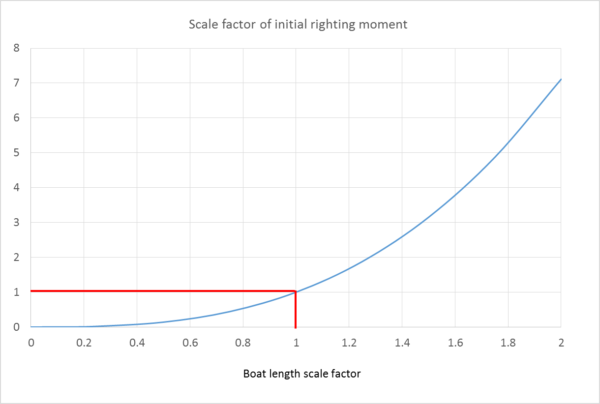
Variation of initial righting moment with boat length
The more annoying consequence is that stability reduces at the same rate for smaller boats, and if the length of the craft is halved, its initial stability is now reduced by a factor of 7, resulting in about 14% only of the righting moment of the full-size vessel.
Just going down from 10 to 8 metres in boat length is enough to wipe out nearly half of the righting moment for a comparable boat. Sea conditions remain the same for everyone out there and, for this reason, a practical size limit is quickly found for small vessels heading offshore.
While very small yachts have completed extensive voyages in fair weather areas, for all latitudes sailing I would be reluctant to embark on a boat smaller than what my 9-metre, 4.5-tonne loaded, Dufour Arpège was. My personal feeling is that, below 8.5 metres and 3.5 tonnes or so, one could start facing a few defining moments. The boat would get knocked around just too easily.
One of the most remarkable sustainable and documented very small boat voyages is John Guzzwell on the 21′ Trekka. It takes a very seaworthy little boat in the hands of a very good sailor to achieve such long-distance voyaging.
Stability Assessment
Positive stability past at least 90° heel is highly desirable for a motor vessel for safety reasons. This is not always achieved, especially in loaded condition. Many older existing vessels have no established stability curve due to their design pre-dating 3D CAD and the effective capability of calculating it.
Small to mid-size offshore sailing yachts are typically required to offer positive stability up to at least 120°. Similarly, only reasonably recent designs benefit from full stability curves.
An inclining experiment is sometimes mandated. This is a process where known masses are shifted in sequence from the centreline of the deck towards the gunnel while heel and freeboards are recorded. A calculation allows assessing the slope of the stability curve for small angles.
An inclining experiment provides no information whatsoever about the stability limit of a vessel. It is purely an assessment of initial stability
In the case of vessels with significant weight stability – deep, heavy hulls – some limited comfort can be derived from an inclining experiment in the sense that stability can be expected to keep increasing steadily to relatively large angles before dropping again. Provided the initial increase is sufficient, maximum stability should prove reasonable and the angle of vanishing stability should occur far enough.
If the hull exhibits significant form stability, all bets are off. An inclining experiment without the hull lines in 3D CAD is next to useless as far as safety at sea is concerned.
When a computer model of the shell is available, the data from an inclining experiment can be used to extract the VCG and displacement; from there, the full stability curve can be calculated. This process is commonly followed before significantly altering an existing vessel and 3D shell models of older designs are often specifically developed for this purpose.