
Last Updated on 17 May 2019 by Eric Bretscher
AIS, for Automated Identification System, is probably the most remarkable safety improvement in decades for small craft offshore. The little project presented here involved designing and building a simple, very low power alarm system to keep an AIS watch at sea.
Collision Avoidance at Sea
Avoiding undesirable encounters with ships in mid-ocean has always been a concern, especially for single-handers. One can sometimes go for weeks without seeing anything, but merchant vessels usually travel at some 15 knots or more and can appear out of nowhere at little notice.
The CARD System
In the early 1990s, a device nicknamed CARD for Collision Avoidance Radar Detector appeared on the market and quickly gained popularity on board offshore cruising yachts, first in North America. Four directional receivers enclosed underneath a little dome picked up the beams of pulse radars and delivered an audible alarm and an indication of signal strength in the quadrant the signal came from.
CARD devices were quite expensive, protected by a patent and handcrafted by a small company in Norfolk, Virginia. The last units seem to have shipped around 2007-2008. The system then disappeared from the market following the death of its inventor and manufacturer.

The well-known CARD radar detector display.
A CARD device, with a very modest power consumption, was one hell of a lot better than nothing and I wish I had had one on board the Yarra. Regardless, whether a ship would keep its radar scanning offshore was always an open question. While virtually all the ones I saw well offshore didn’t, CARD owners were usually swearing black and blue that their devices had picked up all the ships they had seen. Now and then I suggested that maybe they weren’t looking until the radar detector went off, but this somehow resulted in considerable outrage!
I think we were all missing the odd ship going past now and then. I just missed some of the ones with radar scanners in operation, and they missed the others. Together we probably achieved pretty good coverage.
When I tried sourcing a CARD device for Nordkyn, it was too late. In the end, I managed to find a defective one, which I repaired and never installed so far, but this is a different story. The most interesting part was reverse-engineering it. Due to some of the component choices made in the dome, they are all bound to fail from aging after some 15 years or so.
My view is that the advent of the purpose-designed AIS system has now made radar detectors redundant in most situations. CARD devices also performed much better with the S-Band radars used by large vessels than the X-Band scanners found on small vessels. It came down to power, but also to the sensitivity range of the microwave detector diodes used. The development of the low-power broadband radar for small vessels is the other nail in the coffin for CARD systems. The absence of high-energy pulse means no detection possible using this technology.
AIS – Automated Identification System
AIS is a system introduced in the early 2000s that mandated commercial ships to transmit short digital sentences over two dedicated VHF channels on 87B – 161.975 MHz and 88B – 161.025 MHz. Identification data such as the ship’s name and IMO number as well as position, speed and heading are included in the data and messages are repeated every 2 to 10 seconds, depending on vessel speed and movements. The information is used for identifying nearby traffic, collision prevention and routing.
Carrying AIS transmitters was made mandatory for all cargo ships greater than 300 gross tons and all passenger ships by end of 2004. While this leaves out navy ships, fishing ships and some others, it provides for detection of maritime traffic offshore that is undoubtedly far more extensive and reliable than passive radar emissions monitoring.
A number of AIS monitors, receivers and later transmitters appeared on the market for small craft. Realistically, on a yacht sailing offshore, the simple reception of any AIS message is an abnormal enough event, because there is still ample space out there at sea and we don’t enjoy company. Rather than running energy hungry equipment to receive, decode and display AIS data, I just wanted a simple audible alarm whenever a message is received. The range of VHF radio transmissions is essentially limited to line of sight, with antenna height being a determining factor. Reception of an AIS message reveals the existence of another vessel within the reception range and at that point, having a look around for it is more important than the content of the message. Appropriate elevation of the antenna can filter out traffic that is too distant to be of interest, keeping some peace and quiet on board.
AIS Alarming
After briefly investigating building a small VHF FM receiver, I opted for buying a simple low-power commercial AIS receiver instead. One common feature of a lot of AIS receivers is a serial data port for sending out the decoded messages. Designing an alarm circuit connecting to the data port seemed to be a reasonable path forward. I purchased a very compact Smart Radio SR161 receiver, selected for its low power consumption, from a yacht that felt a compelling urge to replace it with a transponder. With a measured current draw of about 60mA only, my SR161 can provide a continuous watch for a daily energy usage below 1.5Ah.
The additional consumption of the alarm circuit in standby doesn’t even register in comparison.

Smart Radio SR161 AIS receiver.
The specification for the alarm circuit included:
- Minimal standby power consumption
- Power on indication
- Visual and audible alarming upon reception of any AIS sentence
- Two levels of audible alarming
- Silent mode
- RS-232 serial data must pass through to remain available for connection to other equipment, such as a laptop, if ever desired
- Power supply to the AIS receiver switched by the AIS alarm system
This should make the alarm circuit compatible with any AIS receiver equipped with a RS-232 serial port.
-

AIS alarm system block diagram.
The AIS Alarm Circuit
The circuit operates as a charge pump, stealing and accumulating a tiny amount of energy from the AIS data signal as it rapidly changes from low to high while spelling out the message.
This accumulated charge is then amplified and a visual and audible alarm is activated until the stored energy has decayed. In the case of a ship transmitting every few seconds, the circuit delivers a continuous, or near-continuous alarm. Intermittent signals coming from the limit of the reception range trigger intermittent alarms.

The AIS alarm board measures 70x40mm only.
A short intermittent flash from a LED indicates that the system is active. Eliminating this functionality would reduce the component count by six. The prototype shown was installed in a small plastic enclosure with the board simply held in place by the threaded shanks of the switches.

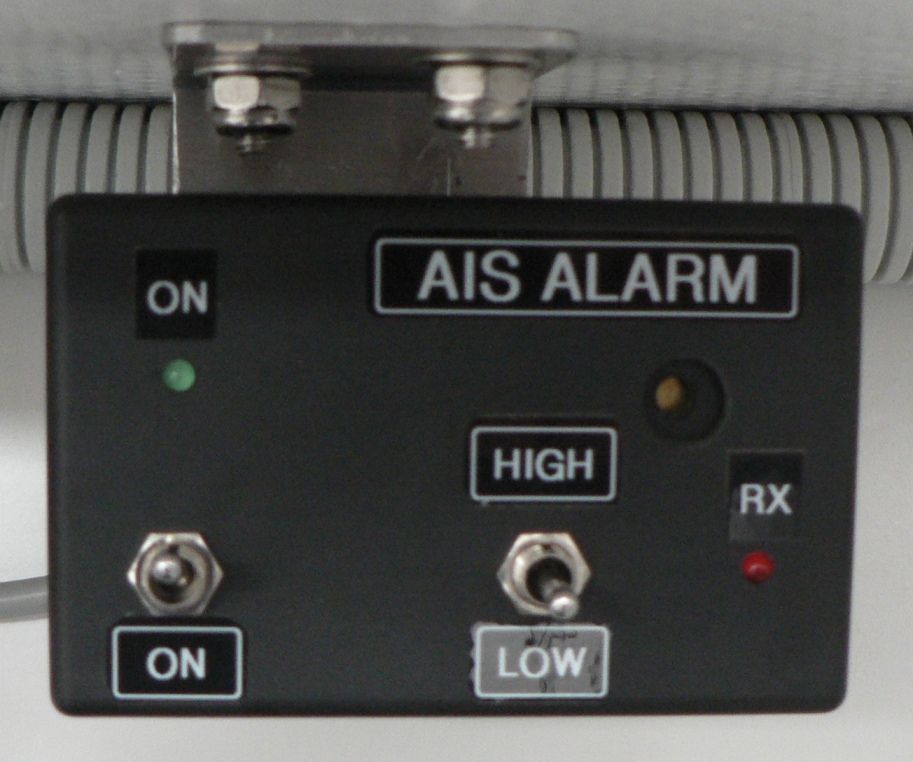
Completed AIS alarm device installed in a small plastic housing.
A small multicore cable coming out of the housing leads to a terminal block where the connections to the AIS receiver are made. The AIS receiver cable uses a standard DB9 female connector; two cores only (GND and Tx) are required to read the messages, but three (GND, Tx and Rx) are needed if one also wants to configure the receiver from a laptop through the same connection.
Building the Circuit Board
I condensed the information required to manufacture the AIS alarm board by hand into a PDF file available for personal, non-commercial use at the entire risk of the builder. It includes 1:1 scale layouts for the circuit board, a bill of materials and the schematic. If you want to get the PCB manufactured by a commercial service, Gerber files are available here, but check that the buzzer and switches you source actually fit the board!

The small circuit board can be home-made quite easily.
The circuit was not tested with other AIS receivers than the SR161, but as long as the signal voltage is sufficient, there are no reasons for issues to arise. For the sake of simplicity, the circuit doesn’t amplify and condition the data signal from the receiver. Before getting started, you may want to check the level of the AIS receiver RS-232 port by measuring the voltage between pins 2 (TX) and 5 (GND). It should usually read around 12VDC in the absence of data being received. If it is noticeably lower, you may need to reduce the value of resistor R1, otherwise a low signal voltage will reduce the duration of the alarm for each message received.
Drop me a line by e-mail if you build one and let me know what AIS receiver you have used.
If you don’t feel like making a printed circuit board and there is no urgency, let me know. If the demand is sufficient, I may arrange a production run at some point.
AIS Antenna

VHF radio and AIS alarm system side by side on board Nordkyn.
Don’t reuse the VHF radio antenna for the AIS receiver, ever! It is senseless. If both share the same antenna and the VHF transmits directly into the input of the AIS receiver, it will fry it. Antenna switches weaken the signals, add complexity and cost more than a second antenna – especially the one described below.
A VHF radio antenna should be located high, typically at the masthead to get a long range, and you should come down with RG-8/U or RG-213/U coaxial cable, which is about 9mm (3/8”) in diameter, not the skinny RG-58C/U commonly found everywhere; it loses too much of the signal at these frequencies coming down a tall mast. On the other hand, an AIS antenna doesn’t need to be installed high unless you are in the business of mapping all maritime traffic in a 30NM radius. For monitoring and alarming, it is desirable to keep the antenna low so it doesn’t pick up ships passing below the horizon and – if you feel like it – make your own: a metre or two of wire connected to the centre conductor of the coaxial cable will make a suitable antenna. While I was developing the alarm circuit, my SR161 was receiving the surrounding traffic from a multimeter lead with the probe touching the centre of the receiver’s BNC socket.
Such an antenna is not suitable for transmitting however. Don’t try, you would risk damaging the transmitter.
Finally
AIS messages are broadcast on two separate channels, in order to provide some robustness in terms of interferences. Some receivers include dual reception circuits and listen on both frequencies simultaneously. Their performance is demonstrably superior in high traffic and they do receive and process more messages.
For the offshore sailor, it is a moot point. If there is any traffic, his or her place is outside dealing with it, not facing a little screen down below, and one ship is enough to prompt attention. Single channel receivers instead switch frequencies every few seconds while listening, and presumably switch if they experience interference. One advantage they offer is lower power consumption and, in the worst case, they may just take a few seconds longer before receiving a well-formed message and triggering an alarm.
AIS “calculators”, receivers that also take a GPS feed and compute projected intersection points between the vessel course and the AIS vectors to filter threatening vessels from the others, are essentially gadgets for the visually impaired.

A peek inside the SR161 is an irresistible proposition. The CPU board is mounted above the radio board, which is missing the components for the second receiver available in the dual-channel model SR162.
Is there any one or Co. That will repair a CARD?
Gary,
I have had in mind to write an article about repairing them, because they are all bound to fail as I explained, but it has remained an intent. Finding the time…
After completely reverse-engineering mine, I occasionally repair them to help people out, using much more durable components than what is originally in them. They are great and it is a shame they are no longer manufactured.
If you e-mail directly with some details and your location, we can talk about it.
Best regards,
Eric
Mine is getting power but will not turn on. I do not know if it is the electronic box or the dome on the back rail. We are on Lake Erie. I can do some rudimentary testing if I would know what to check.
Gary,
The power supply is contained within the display unit and then there is quite a bit more electronics in the dome. Unlike the dome, the display is very easy to take apart, so the first thing you should check is whether the supply makes it past the on/off switch on the sensitivity potentiometer on the board. Bridge over the switch to test if needed.
Getting the green centre LED to come on should be very easy, because it has nothing to do with the more complex circuitry inside the dome. Until then, you can pretty safely assume that the dome doesn’t have power either. I have close up photographs of both circuit boards in my files, I will have a look for you tonight.
Regards,
Eric
Eric,
I have a C.A.R.D. system installed but not functioning any more.
Questions:
– Is there anything else equivalent on the market?
– Can it be repaired?
It turns on, one of the direction arrow does not light up.
It does not receive any more it seems as it does not see my own radar.
Since you have reverse engineered it it seems better use of my time to get your help then doing it myself.
Hello Jean-Francois,
There has been a French product called Mer-Veille on the market that is similar to the C.A.R.D. system, but I am not familiar with it.
A C.A.R.D. system can always be repaired, because it is quite simple and none of the components are difficult to source. The microwave detection diodes can require a bit of shopping around and different models were used over the years.
The spark from a nearby power switch normally sets it off every time, even with detection diodes that can’t see radar beams any more. When this is the case, replacing the detection diodes in the dome is frequently necessary. As I have found a number of different failed components in C.A.R.D. devices, it is not very easy to formulate general recommendations to repair them.
It pays to start with the simplest things like checking for broken wires in the plug and broken solder joints on the display PCB. Next, check for the power supply to the dome. The device operates with four identical channels each coming back to the display unit through their own wire, so you can normally swap the channels and determine whether a channel fault is in the dome or in the display module. I would start with the “bad” channel and work by comparison with the others.
I have sometimes thought about writing an article dedicated to repairing these devices, but it would represent quite a job. If you can narrow the issues down somehow, e-mail and we can discuss them.
Best regards,
Eric
When I looked at the CARD detector and Alarm circuit for a friend it was rather a simple circuit.
The detector diodes were readily available in SOT23 BAT series. I even tried Macom detector SOT 23 diodes.
The Amplifiers were LM388 and the Alarm circuit was dead simple LM3914/LM3915 LED bar driver.
I can dig up all the circuit details. The diodes had a small bias circuit in the head that delivered 50 ua of bias current to increase sensitivity.
When I measured it, it had -55Dbm sensitivity.
I have a Lokata watchman on my boat, if you looking for a replacement that is easy to repair then this is the one to look out for. Any ceramic microwave diode will work like the 1N23 or the small package detector diodes. You can rescue them or buy microwave alarm sensors and rip them out from them.
The reason I like the Lokata is that it has a demodulating mode where you can hear the radar chirp signatures. So if you dont want an annoying alarm going off you can just listen to the CHIRP / doppler sounds. Some boats had peculiar radar signatures I remember seeing a boat in sea then when I sailed in port and heard its squeaky radar I knew exactly what ship it was. It was a North Korean ship that had chirp that sounded like a rusty wheel that needed greasing.
I had both the Lokata and CARD on my boat for testing and I found no advantage to the directional display of the CARD.
Another interesting unit that I have in my collection is a very old Tamaya Marine check radar detector. Its rare as hell. It was the size of a transistor radio and used a 1n23 detctor diode. It had a nice alarm that sounded like a submarine sonar ping sonar. It was super sensitive and i could leave it laying on the chart table and it would detect S and X band radar. It was designed a by experts. It has a plastic lens antenna that you plugged into the waveguide and you could go on deck and direction find the direction of the ship.
Merveille in France makes a copy of the CARD or it has the same concept as the card. If you dont want to fix your CARD buy a merveille marine radar detector. All the mini 6,5 transat sailors love their units
This is a great post, thank you!
I also reversed engineered my CARD device and extracted the schematic in order to repair it. I think you mean LM387 for the signal amplifier. My CARD had failed detection diodes amongst other defective components and these diodes were marked “SH1”, in SOT-23 package. Any Schottky diode can be used as a microwave detector, but some will work better than others. I couldn’t find what they were with absolute certainty, but my best guess based on this marking was Skyworks SMS7621 and I bought some. I also tested with Avago HSMS2860 diodes and played with the bias current by replacing some resistors. This seemed to improve the sensitivity. Detecting the S-Band radars used by ships was always very easy, but the small X-Band pleasure-craft pulse radars were much more challenging. Early CARD units used DDL6672 axial-leaded diodes, as per the US Patent that covered them. Which modern component would give the kind of detection performance that seemed achievable with the old 1N23 is still an open question.
I still own my repaired CARD detector, but it has not seen a lot of use lately because of the type of sailing I have been involved in. Rain radars operated by meteorological services are also in the S-Band and they set off radar detectors every minute or so over hundreds of miles, so coastal use is now out in New Zealand. Last year I was fortunate enough to acquire a brand-new, never used “old” CARD 060 system and I am going to compare its performance against the one I repaired.
The increasingly widespread use of low-power broadband radars on small vessels is a problem for radar detectors. They operate in the X-Band as well, but the power levels seem too low. I haven’t had the opportunity to test whether they could be detected by a CARD system even at short range.
Kind regards,
Eric
A French firm Ciel-et Marine, produces (did produce at least 2022) both a radar warning device and a simple AIS warning device.. I bought the radar thingie, have not yet mounted it permanently but it seems to work when tested in port. Adjustable sensitivity, gives an indication of direction and covers both X band and S band
Thus I have no experience of how it works on the ocean, nor of how well it survives onboard.
http://ciel-et-marine.com/
It is definitely cheaper than a radar and also much cheaper than a Sea-Me Radar Target Enhancer but obviously not the same thing either.