
Shell Construction
This section covers the construction of the aluminium hull and deck, starting with the fabrication of the frames.

The frames were built by welding pre-bent aluminium T extrusions into CNC-cut floors.

Each frame was manufactured on top of a full-scale drawing on a table with a precision tolerance better than 1 millimetre.

T extrusions were too strong to be rolled successfully. Instead, custom tooling adapted to a hydraulic pipe bender allowed shaping them.

Each frame was designed to interlock with the longitudinal girders like a giant jigsaw puzzle.

The cockpit was folded and assembled early to form the backbone of the stern module. More frames are awaiting to be installed to the bottom girders of the main section to form the next module to be connected. The bow section formed the last module.
Setting up must be performed with the utmost accuracy. Laser levelling with reference lines on each frame was used.

The roof top was plated first, holding the centreline of the frames into position, then the side-decks. Deck stringers were cut and added incrementally.

The composite bulkheads, pre-manufactured on a flat table, were inserted into place before hull stringers were added.

Plating proceeded fairly swiftly, starting from the areas without significant compound curvature, progressing symmetrically throughout. Plates are put into place, incrementally welded to the frames first and their edges finally trimmed and tack-welded from the outside. The butt seams are then fully welded from inside as the job advances.
Having a second set of hands on the job would have allowed working with one person welding inside the hull and another holding the plate in position from outside. The gain in efficiency would have been nothing short of phenomenal.

Nearly all plates were wheeled. Heat-treated marine-grade aluminium sheet is too stiff and strong to be pulled into shape on the framing. Most plates were half-a-sheet wide, or about 900mm.
The short curve is the most important one to obtain by rolling; the long curve can be progressively forced in to some extent, taking advantage of stress relief when welding. While somewhat crude, the wheeling machine was invaluable. Don’t even think about plating a round-bilge hull without forming the plates, or by using rollers and plating diagonally, as it was sometimes suggested to me.

Plating continued into the areas of heavy compound curvature – the turn of the bilge near the main beam – and the tight spot where the bottom meets the stem, using smaller, more manageable plates.

Staying on top of the job is essential as the slippery slopes become more pronounced! The ground is a long way down.

The bottom of the forebody was plated using a single piece, no seam on the centreline, one of the most difficult plates to shape and get into place, but still achievable as a one-man job.
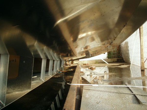
The hull plates hang below the deck edge. After a lot of overhead welding, the toe rail was built by boxing between the deck and the hull plating with aluminium angle.
Finally, all the plate seams are gouged back from outside to reach the root of the inside run and flush-welded, resulting in a full thickness weld with a bead inside. MIG is the only suitable process for welding an aluminium hull due to limited heat input. While most photos were taken in daylight, a lot of the work took place late at night like here.

The open transom was the main access way to get in and out for welding. It was left open for as long as practical. I must have gone through literally hundreds of times while manufacturing the shell.

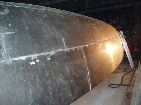
Filling and fairing is a dusty job and a good workout. It followed sandblasting and sealing the metal using an excellent anti-corrosive high-build epoxy primer. Epoxy resin and glass epispheres were used as low-density filler below the waterline, phenolic resin microballoons in the topsides as they were supposedly easier to sand. There was no difference sanding either filler and epispheres were a much better and cheaper product.
Fairing amounted to an average of 2-3 millimetres. No sandblasting photos as there isn’t a minute to waste between blasting and sealing the surface.

A startling amount of high-build epoxy primer was literally poured out of the spray gun onto the faired hull to encapsulate the filler. The bottom was then sanded again smooth, primed with more high-build epoxy and a single thin tie-coat of hard antifouling was sprayed on. There is nothing worse than having to sand a hull from underneath. This approach ensured that the antifouling would later be able to be sprayed following a simple high-pressure wash.
The last task before turning the hull over is test-fitting the hollow keel foil into its slot. It is much easier to play with the 200kg foil up there while trimming the slot than repeatedly raising and lowering the entire shell over the keel later.

First look down-below, into a little world now upright for the first time. The hull was rolled over in slings between chain blocks. One of the first tasks coming up was now etching and painting the bilge plating up to the waterline with high-build epoxy primer. All alloy vessels should have painted bilges, even more so commercial workboats that are seldom as dry and clean. It saves having to deal with pitting issues down the track.
Some areas of the roof were not able to be plated until now, as steel supports were coming through from the ground. It was also good to be able to close this deep hole before falling into it. Later, I instead elected to fall through a large hatch opening covered by a tarp – without much in the way of adverse results.

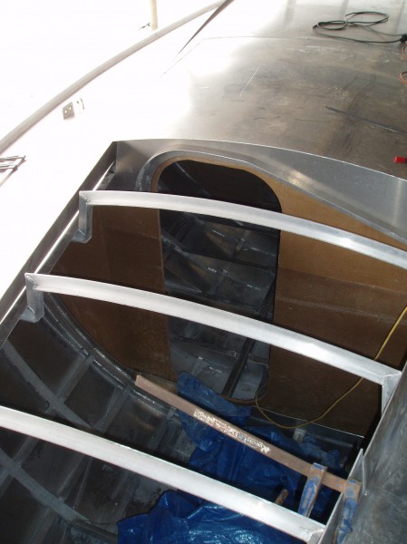
The roof sides can now be plated. At first, the roof was plated to hard edges, but the seams were not welded.

Finishing involved re-cutting the edges in place and forcing in a split section of pipe to achieve radiused corners and soften the shape. Windows were cut and frames added, the sliding hatch constructed, hatch openings cut… At this point, a lot of the deck hardware needs to be available already in order to be fitted.

Building good sliding hatches is a renewed challenge each time. The hatch must be able to resist considerable flooding from above, operate well and ideally never wear out its slides.

Completed deck plane. Cleats were anchored through the deck into the frames and machined stanchion bases welded in. There is nothing worse than through-bolted stainless steel stanchion sockets on an alloy boat. The roof top hand-railing is also integral to the construction.
Construction of the appendages is described here.
Great job!
I’m amateur builder and I’m preparing for building own round bilge hull (but in steel) and I wanted to ask about wheeling.
And when I saw your work and result of wheeling I was positively suprised.
The shaping is made by a stress in material, so the thickness of the metal sheet is changing right?
So how much this change of thickness is?
Hello Peter,
Thank you for your kind comments. Building round bilge hulls is much easier than it looks.
Practically, the variation in the thickness of the plate due to the forming process would hardly be measurable, because you always try to “gain” very small amounts of material over relatively large areas. When wheeling aluminium plates, you never crush the plate between the wheels, it is not a laminating process.
In my case, the bottom wheel was hollow V-shaped and the top one was full with a light curve only, so it wouldn’t press a ridge in the material. Obtaining the shape was really achieved through a combination of wheeling, stressing of the plate over the framing and yield of the material during progressive welding to the frames under tension. I wish my wheeling setup had been good enough to obtain the full compound shape, but it wasn’t by far and marine grade aluminium is incredibly stiff. I mainly wheeled the “short” curve in my plates, and I obtained the other one when fitting and welding the plate into place. When an edge occasionally buckled, I cheated and put a short saw cut into it and welded it to “lose” some material.
With steel, I am not sure I would go about it the same way. You have more options. If you sandblast a steel plate on the ground, it will curve like a spoon and come up. You can also shrink its edges by heating them with a torch and letting the metal cool down (this is absolutely out of the question with aluminium, because the sheets are heat-treated for strength). I have heard of people who plated beautiful round-bilge steel hulls with very little mechanical forming and this is how I would approach it. It also depends a bit on how thick your plates are going to be.
Start in an area that is easy on your hull and get a feel for what the material will do for you. If it is too hard, don’t force it. Stop, think and find a better way. I had a 1:10 scale model of my hull and I played with a piece of cardboard to get a feel about the way I should arrange the seams. It is usually a good idea to plate the sides and the bottom with the largest plates you can shape and fit (within reason), and then you are left with closing the gaps around the turn of the bilge using smaller plates.
Plating a metal hull is fast and very rewarding, so all the best with your project!
Best regards,
Eric
Thank you for information. Now everything is clear: bottom bending roll is hidden, so thought there is a “barrel” roll.
Right now I’m making some research about home made wheeling machines, because my Ankon 40 will be build from steel up to 6mm (at the moment I’m waiting for plans and later I will have a lot mor work to prepare everything but I’m stubborn pearson and that’s perfect for my motivation). So the machine should have extreme stiffness and of course some drive.
Every tips and tricks are welcome. So again thank you!
Best regards,
Peter
Peter,
The bottom roller can be one roller wider and with more hollow that the top wheel, two separate wheels… many configurations work. My wheeling machine was powered and it made it slow, but some people have built boats pushing and pulling the plates underneath the wheel. The shorter your distances between the pressure points, the more force is needed and the more likely the need for a motor.
6mm steel sounds extremely heavy for just a 40′, hopefully it is confined to very small sections of the plating. Remember that the thickness of the hull is not a parameter you can freely modify to suit your own ideas, there is some relevant information about this on this page.
Best regards,
Eric
For luck most of the hull is 4mm plates and deck 3mm, but the bottom next to keel is also round and it is from 6mm thick steel.
I was looking for some wheeling machines but only source of heavy duty e-wheeling machines I have found was in New Zealand. I have some basic details about the frame for that kind thick steel plates, so I think I will build it, just waiting for plans to figure out what wide plates I will have to use (shorter arm of the wheeling machine less I-beam high needed – I don’t want to overinvest in machine I will use just once, and I don’t to make to “small” machine).
Thank you for the link. I have already read some articles from your site, they’re very helpfull.
Again thank you for encourage words.
Peter
Hello!
After long time of hold on I’m back to the project of my steel sailboat. I’m preparing to the crowdfunding start.
Because I think your site is very interesting and have great knowledge (and in return for sharing information about bending machines) I also put a link to Nordkyn Design at my page.
Thank you again!
Thank you Peter, it is nice to hear from you again. I wish you all the best with construction. Building a yacht is a great project with a lot of satisfaction in it.
Eric
Hi Eric,
Is that plate on the bottom of the forebody similarly thickened like the one around the keel socket?
I wonder, too did you flange the inside of all the floors and bulkhead/partition frames and where you did, was it to stabilize the web and/or provide attachment grounds or both?
Cheers – Peter
Peter,
The plate in the forebody is the same as everywhere else of course. There is nothing special there. The only difference is that the stringer spacing is less forward.
Folding floors and girders is a standard way of building the equivalent of an I-beam once attached to the plating and it keeps them straight. The flanges are important as they work in tension and compression.
Eric
Thanks Eric,
Although I am surprised to hear that the stringer spacing is LESS forward – I would have expected closer spacing in this high-load area.
Also, at what point in the hull build did you weld in the frame/deck beam ‘knees’? I’m guessing after plating.
Regards – Peter
Peter,
Saying that spacing (=distance between) is less means that the stringers are closer together, which is what you should expect in areas where the design pressures are higher, such as the forebody.
The knees were welded into place after plating indeed in this case, in order to minimise distortion. Today I would terminate the extrusions into CNC-cut corner pieces and they would be integral to the frames as they come off the table. It could make construction a bit easier in this area.
In the sail locker forward, the frames and deck beams were also braced together using a length of T-extrusion each time.
Regards,
Eric
Thanks again Eric, this old duffer got it quite wrong. Of course less means closer not fewer.
Cheers – Peter
Hi Eric,
So in the sail locker you used T-extrusion as well as or instead of plate knees?
Also did you insulate the sail locker and is it fully ‘bulkheaded’ from the chain locker.
Regards – Peter
Peter,
In the sail compartment, the deck beam is heavily welded into the frame and the corner is braced with a T-extrusion. Those are about 500mm long, it is not going to move.
The sail locker is not insulated, and neither is the lazarette. There is no need. If it is cold forward, I just close the watertight door.
The chain locker is “outside” and fully separated from the sail compartment. The bottom of the chain locker is sloped and above the waterline.
Regards,
Eric
Hi Eric,
How did you fasten the composite bulkheads to the adjacent ring frames? And what are the ‘dots’ around the margins?
Thanks – Peter
Peter,
They are both bonded to the aluminium with urethane and through-bolted all around. The core was removed around the bolts, so the skins could be brought together and the glass thickness increased. The bolts were fully tightened only after the urethane had fully cured.
Eric
It is a magic process! Thanks for your share and explanation of how to plating aluminum alloy plate.
I am a shipyard designer and eager to have a boat of my own. And working with steel ship during my whole working life, I have no idea to construct an aluminum alloy boat,especially for forming compound curvature. So these days I had read lots of articles about working with AL alloy, and then it is an encounter of your essay.It is a shining guideline for my coming personal project.
whats more,I would like to express my collections which also need to be proved practically.
1. laying off the hull shell with one curve direction of the dual curvature. And the only thing to do is to wheel along another curve direction. (it is proved, from the steel boat hull design book)
2.heating the AL alloy until 100-200¡æ,and its elongation increases and it is easier to work.And I think it is also suitable to other AL alloy. But I have no way to check the right 5083-H112(or other types,like 6061-T651) metal phase diagram and the authoritative experimental date. (to be proved,from a repair manual of Porsche)
Thanks to your share and look forward to receiving your reply.
Dear Xinpan,
My apologies for not replying earlier, your message was unfairly caught by the spam filter. I have just found it now.
When it comes to forming perfect compound curves in aluminium, it is quite difficult unless you have a very good wheeling machine and you can work freely in all directions. This is not a real problem however. I found that the most important curve to shape in the plate is the short one following the frames, because the material is far too strong and stiff to be pulled into shape. Once you have the correct shape for the frames everywhere, you can clamp the plate against the framing from its ends and it might only touch some frames in the middle. When you start welding it under tension where it contacts the frames, it yields a little and the “ends” start coming down naturally, so you can reclamp it tight again and keep welding. It just gradually gets into place.
If an edge buckles a bit (which can happen, because you were unable to stretch the centre of the plate enough), put a saw cut into it to allow it to collapse back to flat and then weld the cut later. These cuts are typically only 100-200mm long from the edge and not needed very often. In most instances, when you fully weld the seams later, stresses in the plate edges get relieved.
The other piece of advice I would have is plating everything that is easy first. It leaves much smaller plates in the areas where there is a lot of compound curvature and small plates are a lot easier to work with.
I don’t think heating 5083-H321 plate would make much difference or help, unless you heat it a lot of course. In this case it loses a lot of its strength and you don’t want that at all. The same applies to the heat-treated 6000-series alloys and T6 is especially strong. Softening it is not the objective. You need to cold-form everything and control the heat when you weld it to preserve the strength of the metal. I never heated any plates and I would never to it.
Forming a round bilge hull is a gentle, gradual process. It never involves applying huge forces. If it gets too hard, you need to stop, think and find a better way. You are doing something wrong. It is not as difficult as it looks and you need to make the material and welding all work for you and help you. If you try fighting the material, you will usually lose because these grades for marine construction are extremely stiff and strong.
Kind regards,
Eric
Dear Eric,
Congratulations Sir, few people can design their own boat and come up with such an amazing and professional looking product. I have really enjoyed reading your blog, inspirational!
I wonder, you have used fewer stringers than I have seen in other pics of Al construction. I guess you have gone for toughness over weight saving, would you have saved much weight with stringers, did you consider this?
You have amazing blue water cred yet you defy popular trends; no dodger/shelter, no bimini/surface for solar panels, no wide shallow open cockpit space for lounging at anchor, I’m guessing there are good reasons for these things. Will you fit a dodger for Alaska and such inhospitable places?
Did you consider reducing the cord of the keel near the bulb to reduce pressure there?
Did you consider a lifting keel in a centre case, (same no compromise shape and weight/ bulb), (lifting transom hung spade(s))? (This is my ambition and dream but I have no idea of the engineering or practicalities. I sail an E 770, sailors boat, hull shape and concept not dissimilar to yours but small scale and with just 350kg in the bulb the lifting is relatively trivial.)
Did you make that beautiful sailing machine in sleepy Oamaru, near the Little Blues? Looks like that in some of your pics.
Appreciate your feedback. Thanks
Best
Ross
Hello Ross,
Thank you for writing. The stringer spacing is a function of the hull plate thickness, frame spacing and curvature of the hull in the area. A round bilge hull is intrinsically a lot stronger than a chine one and requires less stringers. Everything is also designed to withstand the local design pressure and, as this is partly a function of vessel displacement, a light vessel doesn’t require the same structure that would be found on a heavy displacement hull of the same length. There were also constructional considerations because thin plates distort a lot more with welding, so I investigated a few different options with regard to framing and plating and decided to keep a bit more thickness in the hull plates. The difference in terms of weight was not much, but a slightly thicker hull is much more difficult to dent or breach.
It was beneficial to have a parallel shape for the keel foil as it is slotted into the hull and floors and it had to be able to be inserted after turning the hull over. The interactions between the planform, the hull, the bulb and the centre of pressure are complex and strength is an extremely important aspect in the design of such a keel. Having a continuous, unwelded plate on each side of the foil was far more essential than a tiny hypothetical gain originating from a different planform for example.
I did very briefly consider sliding the keel up, but no matter how you do it, the mechanism adds significant weight to the boat and the same weight is best placed in the bulb. It is also a lot more fragile, complex and costly than a fixed welded keel, for very little benefits because I hardly ever faced draught constraints in my travels. I do not like shallow water and/or being very close inshore, because there is no margin and/or warning if something unexpected happens. A transom-hung rudder loses the end-plate effect of the hull and is a lot less effective.
You need to remember that “popular trends” are not set by people who sail according to my definition of sailing, and sailing ability is in fact a long way down the list of their priorities – otherwise the boats would not look the way they are.
I personally find the cockpit the least desirable place where to be on board and, when I am there, it is for manoevring and I want to be able to work efficiently and see what I am doing. When there is nothing to do, I stay inside where it is far more comfortable, I don’t get fried by UVs and I have excellent visibility through the windows. On a great many boats, the dodger is such a hindrance for line handling and operating winches that they can no longer be sailed efficiently and you can’t see forward from the helm any more. I don’t actually see the point of having a dodger for sailing the way I do. The sliding hatch comes back far enough to protect the companionway in most conditions and it is possible to sit there, almost outside and still protected.
The other aspect is windage and seaworthiness. Every time you increase windage, the upwind angle deteriorates. In a breaking sea, anything and everything exposed on deck is candidate to be carried away. In heavy weather, the sea can wash over the boat and run off unimpeded and there is nothing to worry about. It would be great to have more solar panels at times, but the present arrangements can withstand any weather and don’t impact the boat’s performance and this is far more important.
I built in Bluff as circumstances were favourable at times and all construction photos are from Bluff as a result, but I have been coming to Oamaru for a number of years.
Kind regards,
Eric
Real nice job, congrats !
Just for info what is the thickness of this forebody bottom plate ?
Pretty strong curvature, must have been a real challenge to put in place on your own !
The whole bottom plating is 5mm, except around the keel where it is 8mm. I rolled and pressed the plate in a V-pattern from the outside towards the centerline before putting it in. I only pulled it quite minimally. Just pulling it in would be impossible, the material is incredibly stiff.
Kind regards,
Eric