
Last Updated on 17 June 2018 by Eric Bretscher
This article is part of a series dealing with building best-in-class lithium battery systems from bare cells, primarily for marine use, but a lot of this material finds relevance for low-voltage off-grid systems as well.
This article discusses the protection of lithium battery banks in the context of marine installations. A previous article detailed the design and assembly of such lithium battery banks. Before a lithium battery can be put into service, it must be protected or the first adverse event to occur will damage or destroy it.
Disclaimer
A good understanding of DC electrical systems is needed to build and commission a lithium battery installation. This article is aimed at guiding the process, but it is not a simple blind recipe for anyone to follow.
The information provided here is hopefully thorough and extensive. It reflects the knowledge I have accumulated building some of these systems. There is no guarantee that it will not change or grow over time. It is certainly not sufficient or intended to turn a novice into an electrical engineer either. You are welcome to use it to build a system, but at your own risk and responsibility.
Battery Protection, Battery Management or Both?
The needs of lithium batteries fall into two categories:
- Requirements to be met to prevent dangerous developments, damage or the rapid destruction of some or all of the cells.
- Requirements to ensure a long operating life and an absence of issues over time.
The first category represents acute needs which must covered by battery automated protection functions; the second one pertains to battery management. Battery protection must be seen as the basic subset of functions battery management is built upon: there is no management without protection, but at the lowest acceptable limit a lithium battery can be protected without being automatically managed.

A 200Ah DIY lithium battery back for a yacht connected to a custom battery protection module.
From left to right on the connector, the four cell voltage signals, the reference negative, the two power supply cores for the module itself and the cables from the temperature sensors. Using the right equipment considerably simplifies the task of building lithium battery systems.
Battery Protection
An unprotected lithium battery can become a fire risk or an expensive fiasco: take care of the cells and the battery will take care of itself
A lithium battery cannot be responsibly operated without a layer of protection between itself and the electrical installation because:
- Lithium cells are quickly destroyed by voltage excursions.
- Excessive discharge causes severe and irreversible damage.
- Overcharging a lithium battery, or recharging it in a damaged state, can overheat it to the point where it can ignite and burn extremely hot.
Protection is simply a matter of keeping at all times each and every cell within its allowed operating voltage limits and ensuring nothing ever begins to warm up. Give or take a few degrees at high sustained currents, a lithium bank on board should run at ambient temperature, at all times, no exception.
Integrated short-circuit protection is also commonly found on small battery packs, but it is problematic to implement on larger banks, such as found on marine vessels, because the potential fault currents can exceed the interrupt rating of the disconnectors; fusing must be used for this purpose. Also, due to the relative size of the battery and wiring, the risk is not so much towards the battery: something else is likely to melt or get destroyed first.
A protection system must be able to act automatically at any time in case of detected issue, before a serious situation develops. Alarming is pointless for that matter: alarming relies on someone not only being present, but also understanding what is happening and knowing what to do. The human factor becomes embedded into the reliability of the scheme and momentary inattention or absence instantly results in zero protection. It is only a matter of time.
Battery protection is therefore the first and most essential layer of any lithium system, because it implements all key safety functions and protects the asset. It needs to be built and engineered correctly. A number of devices are available on the market to perform this task, with wide variations in quality, reliability and suitability for a marine installation. Interestingly enough, some people have routinely installed junk-grade gadgets on large expensive assets without even blinking an eye, while others simply dispensed themselves from installing anything… As we all know, accidents always happen to others, but the banks I see destroyed seem to be those, a curious paradox.
Cell Voltage Monitoring
The need for monitoring the individual cell voltage is the main point of distinction between a lithium battery bank and a lead-acid one, where total battery voltage only is ever considered. It is made necessary by the fact that voltage excursions quickly become destructive with lithium cells and lithium cells stop accepting current when fully charged, which prevent a battery from self-equalising the way lead-acid ones do.
In order for a LiFePO4 cell not to fail, its own voltage must be remain at all times with a prescribed range, above 2.0VDC in all cases and below about 3.65VDC. Practically, cell destruction occurs at about 4.2VDC, when the electrolyte is decomposed, but voltages in excess of 3.55VDC don’t make much sense and the cells are sensitive to the maximum instantaneous voltage they are exposed to, not just the average. Many charging sources deliver a voltage superimposed with a ripple and the peaks from the ripple can destroy the cells even if the average value as reported by a multimeter appears acceptable.
Low-Voltage Protection
The obvious purpose of low voltage protection is ensuring that no cell ever gets excessively discharged. The practical low voltage limit of a lithium iron phosphate cell is typically 2.5-2.8VDC. In the case of a 4-cell, 12V-equivalent configuration, one can argue that sufficient low-voltage protection can be obtained by monitoring the total battery voltage:
The worst-case scenario would be reached if three cells were fully charged (3.35V open-circuit) while the fourth one was very low.
Considering that a balanced pack is below 15% state-of-charge at 12.8V, even adopting 12.6V as battery low cut-off voltage would give a lowest possible cell voltage of:
VCell_Low = 12.6V – 3 x 3.35V = 2.55V
This is still an acceptable value. However, this result does not extrapolate at all to a 24V installation with 8 cells in series.
Low-voltage protection requires the automatic disconnection of the loads from the battery, so the lowest cell voltage doesn’t sink any further and this is absolutely essential. Such an event is referred to as a Low Voltage Disconnect (LVD) or Low Voltage Condition (LVC) disconnect. Reconnection must not take place until the lowest cell has been recharged up into its normal operating range.
Cell-based low-voltage protection is what allows taking full advantage of lithium batteries, because it allows discharging almost fully when needed without any concerns and it maximises the available capacity and performance of the installation.
High-Voltage Protection
High-voltage protection is obviously related to charging and a similar calculation, even based on a modest end-of-charge voltage of 14.0V for the same 4-cell configuration, shows that protection must be based on individual cell voltages:
If we consider three cells out of four at a mid-range voltage of 3.3V, which is not a worst-case scenario, we can calculate the voltage of the fourth cell as follow:
VCell_High = 14.0V – 3 x 3.3V = 4.1V
A LiFePO4 cell at 4.1V is far into destruction territory and it is clearly impossible to guarantee that no harmful voltage excursion can take place if only the overall battery voltage is being monitored.
There is no alternative to cell-level monitoring and automated protection with lithium batteries
Cell level protection is required here for ensuring charging safety and, should any cell drift towards an unacceptable voltage, charging must stop. This can involve automatically disabling the charger(s) and, if this doesn’t appear effective, the battery must be automatically disconnected from all charging sources: this typically means disconnecting the charge bus, an event referred to as a HVC disconnect. This should always be treated as a serious issue: a HVC event indicates that something is not in order in the installation and the charge bus should not reconnect unless the battery is significantly depleted.
Since cell-level voltage measurement is mandatory for charging safely, it can just as well be used for over-discharge protection too. Cell-level protection is the minimum standard for operating a lithium bank.
Cell Over-Temperature Monitoring
Monitoring the temperature of the cells is highly desirable for the simple reason that temperature is always involved when the situation starts going seriously wrong with lithium battery cells and it provides a second view of what is happening in a battery pack that is completely independent from the voltage information.
In most instances, voltage deviations will highlight problems first, especially in simple series topologies such as 4S or 8S. When parallel blocks of cells are used, voltage monitoring applies to each block only (because the parallel cells all share the same voltage by definition) and temperature monitoring can provide a more granular view of what is happening. Temperature sensors can be inserted between the cell casings and therefore any one sensor can monitor a pair of cells. Full temperature monitoring can therefore be achieved with a number of sensors equal to half of the number of cells.
LiFePO4 cells should ideally be operated between about 10°C and 25°C, but safety concerns only develop at very high temperatures. The absolute maximum temperature a bank should be allowed to reach depends a lot on the environmental conditions it is exposed to. A LFP bank should ideally not be exposed to temperatures exceeding 30°C to prevent premature aging; in this case, a temperature as low as 40°C could be used for alarming. A high temperature should eventually lead to a complete system shutdown and disconnection of the bank. The consistency of the temperature readings within a bank is a lot more valuable piece of information. A marine house bank should always operate within a few degrees from ambient temperature and discrepancies between cells are highly suspicious. The recommended maximum allowed temperature deviation within a lithium battery bank is 5°C from highest to lowest [1]. Any value exceeding this should be investigated, regardless of what the actual absolute temperature is.
Do Not Ever Rely on a Battery Monitor for Protection
Battery monitors with configured high and low state of charge limits are not suitable devices for protecting lithium batteries. The state of charge displayed is merely a completely unreliable estimate obtained by accounting for charge and discharge currents over time. If the battery is cycled for a period without ever being fully recharged, the monitor has no opportunity to reset its capacity count (provided it was configured to do so in the first place).
Protection must be implemented based on the voltage of each individual cell and the capacity estimate made by the instrument is irrelevant. Cell voltages are either within range, or they are not, and they are all that matters.
Do Not Confuse Protection and Control
A protection system with automated disconnection is just that: a last line of defence that should never be activated. Using the disconnection device(s) to terminate charging (a suggestion often formulated by DIY implementers) is out of the question. It breaches the system design boundaries, where the battery protection layer’s role is to mitigate any failure in the charge control system. More specifically, one role of the BMS is defending against a failure in maximum charging voltage regulation.
Several owners of lithium banks I know came to grief with the battery protection layer after making alterations to their charging infrastructure: as it should be. In such circumstances, people sometimes complain about the protection when they should in fact be looking at the consequences of what they have been doing.
Battery Disconnection
Protecting the battery as an adverse event is developing eventually entails disconnecting it. There are three types of devices that can be employed to this effect and, each time, they need to be able to cope with all the current that can be expected in the installation. Battery disconnection is a feature in all battery management systems and most of them can only handle a specific type of disconnector, so discussing the pros and cons of the disconnection schemes is relevant. One may rule out a BMS because it cannot control the type of disconnector best suited for the application.
Regardless of their type, high-current contactors can be designed for the current to flow in a specific direction. This can be somewhat disconcerting, as a simple metal contact obviously conducts independently of the direction of the current, but this is ignoring the effect of the magnetism produced by very high currents. This magnetism can interfere with the one from the energising coil and affect the operation or reliability of the contactor. If the datasheet specifies the direction of the current, follow it.
Mechanical Contactors, or Relays

Tyco Electronics EV200 contactor.
In a mechanical contactor, a coil holds a contact closed when energised. Such devices are also termed “monostable” as they can only be in one state when not energised. Their drawback is the continuous drain arising from the coil current. There are wide variations in coil power between contactors and this will determine the standby power drain of the system, so it is very important to pay attention to the coil current data. Some contactors have built-in measures to reduce the coil current once the contact is closed (holding requires less power than closing), or the addition of an external capacitor and resistor can deliver a similar result, see below. In this case, the capacitor must be large enough to cause the relay to close while it charges and then the resistor must be low enough to still reliably holding the contact closed while reducing the current.
When power is switched on into a coil, the voltage increases relatively gently, but upon turn off, the abrupt collapse of the magnetic field causes a spike (also known as back EMF). The higher the coil power, the stronger the spike. This spike can cause the equipment controlling the relay (i.e. the BMS) to fail, so it should be neutralised using a free-wheeling diode. Some relays have this diode built-in and the coil has a polarity as a result, some haven’t and it should be added externally.
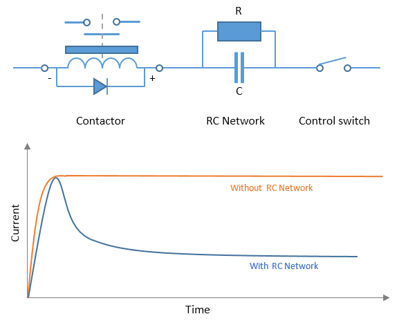
Monostable contactor with external RC network to reduce the holding power consumption. When the control switch is closed, the inrush charging the capacitor C closes the relay contact. The current then reduces to the value determined by the coil resistance and the external resistance R. Without the additional components, the coil keeps drawing full current continuously.
The expression “fail-safe” is sometimes used in relation with (and to promote) simple contactors, because a power failure results in disconnection. That is all very well, but there are far worse and more insidious failures modes than a simple power loss, as discussed further in the section about reliability, and this type of configuration doesn’t automatically fare very well in a Failure Mode and Effects Analysis (FMEA). The outcome of the most common control failure (rather than power failure) usually is that the relay can no longer open because power to the coil can no longer be interrupted. Since the normal state of the contactor is closed when the system is operating normally, such a failure only becomes apparent when a need arises to disconnect, i.e. in an emergency.
Solid-State Relays
Solid state relays emulate the operation of a mechanical relay by using MOSFET transistors instead of a coil and a contact. The advantages are immediate: the control current is very low (technically zero after the device has switched, but the drive circuitry usually adds a small consumption) and there is no arcing or contact damage, as there are no contacts.
However, MOSFET transistors can easily be destroyed by voltage or current spikes and, when they fail, they nearly always do so by short-circuiting completely. Another technical consideration is that such a switch normally has a polarity and it only operates “one way”. When polarised in reverse, the device conducts like a diode and a high current will result in overheating and the complete destruction of the unit, unless it was specifically designed to also block reverse current. This is far from always the case as it requires using back-to-back MOSFETs, i.e. twice as many transistors for twice the losses, heat and cost.

Solid-state relays have no contacts and offer minimal power consumption, but they are usually polarised – like this Victron unit – and can only interrupt the current in one direction.
In a typical small craft marine installation, the disconnectors must be able to handle several hundreds of amps and they can be exposed to voltage transients from starter motor or windlass motor switching. Should the unit fail as a result, it will almost invariably fail short and leave the battery permanently connected. This is not a good prospect in a safety system. Disconnecting the charge bus must also prevent the battery from draining itself into a damaged charger for example, so the disconnector must fully isolate the circuits. Building a suitable solid-state switch is possible, but far from cheap. Solid-state switching is best suited for relatively small battery packs operating in well controlled conditions.
Latching Relays
A typical latching relay has two coils instead of one and a mechanical contact that can stay either opened or closed. Power is only required in the form of a short pulse to one of the coils to change the state of the relay, so there is no on-going consumption associated with the device. This, and the fact that the contact itself can withstand tremendous abuse compared to a solid-state switch, tends to make it the preferred solution in marine systems that are in service 24/7. The coils used in latching relays are not usually rated to remain energised for long periods and they will quickly burn out if left powered. Some larger latching relays sometimes use a small motor to open and close their contact.
The drawback of latching relays is that they require a different control logic with two commands instead of one and so they are not interchangeable with standard holding relays.
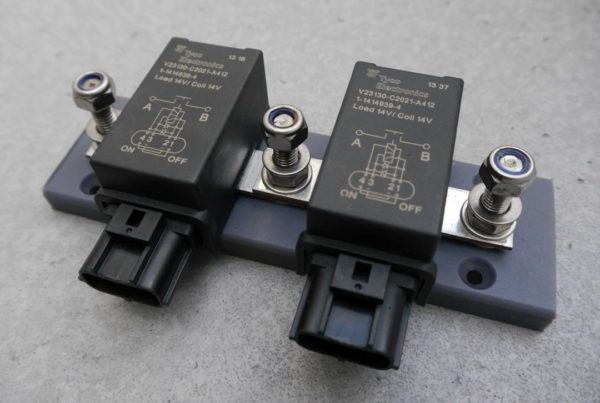
Tyco Electronics BDS-A latching relays with zero standby consumption and a 260A continuous current capacity. The peak current is 1500A.
A control failure means that the device stays in its last state, either opened or closed, and this is generally not a pleasing prospect either. However, since the control circuitry is only operating briefly for switching and spends its near-whole life inactive, ensuring and monitoring its integrity can be achieved much more successfully.
Battery Management
Battery protection doesn’t guarantee that the bank will offer a long service life; it only ensures that no dangerous development can take place and that the battery can’t be quickly destroyed. Battery protection systems operate by enforcing operating limits on cell voltages and temperatures to prevent accidents, but they are unable to prevent lithium plating damage due to reduced-voltage overcharging, or loss of capacity resulting from keeping the cells at a high state of charge for example.
Battery management includes functions beyond protection. The purpose of a battery management system is ensuring that the battery is operated as close as possible to the optimum. This means:
- Deciding whether charging is necessary
- Deciding whether charging should be prevented
- Deciding whether discharging is acceptable
- Ensuring the battery doesn’t remain idle at a high state of charge for long periods of time
- Ensuring that the cells remain balanced over time
- In some applications, provide thermal management of the battery to keep it within an acceptable temperature range
Most battery management functions rely on knowing the state of charge and therefore battery management is not possible unless battery current information is provided to the BMS. Basic battery protection is quite simple and straightforward, battery management is not; it can involve sophisticated decision-making algorithms.
Battery Management Systems
The term Battery Management System (BMS) is used indifferently for devices that provide protection functions only or protection and management functions. Regardless, the most essential function here is a safety one, as stated earlier. Management, if present and well implemented, can ensure longer cell life and consistent performance over time regardless of the regime of utilisation of the bank.
Critical Features
The following must be achieved for effective battery protection on board:
- Individual cell voltages must be measured. Problems with lithium batteries always occur at cell level.
- Overheating must be detectable. When things go very wrong with lithium cells, heat is nearly always involved. Heating is what can eventually lead to thermal runaway and a battery fire.
- The system must be able to automatically act to prevent cell damage. This means eliminating the cause of the problem by disconnection. Alarming is not good enough. Human-powered systems, involving alarms, watching, monitoring and taking action when something goes wrong will always fail in short order: the first time no one is around or paying attention.
- The protection system must be reliable and resilient, it must be protected from voltage transients and not be able to fail unnoticed. Having a level of redundancy and a self-checking ability is highly desirable in a marine BMS, because we are protecting large assets worth much more than the battery.
- The BMS must not induce uneven drain on the cells, or it will throw the bank out of balance and create problems in very short order. This was an issue with some early junk BMS contraptions and it caused a few people to start clamouring that “BMS were harmful”. Using with decent equipment to begin with goes a long way.
- The intrinsic consumption of the BMS solution must be as low as practically possible, or it may drain the battery to destruction in the absence of power for charging. Boats can end up spending winters with snow covering solar panels at times, with little or no energy input and the installation must tolerate these conditions. This generally weighs against solutions that require holding contactors closed. Battery banks drained flat by the BMS also caused some people to claim that any electronics added to the battery were “harmful”. If the cells get low to a point where it is obvious that recharging is not taking place, a BMS must be able to shutdown the installation as well as itself to preserve the battery.
A system encompassing the features listed above will prevent an accident with the battery and ensure the cells cannot get damaged. It could however cause damage to other equipment on board if it gets triggered, so a few additional features are also desirable and correct electrical design is essential.
Essential Features for Marine Installations
Marine applications, especially on ocean-going vessels, tend to place higher requirements on the systems than what would be found in other applications where power availability is more of a convenience.
Availability and Resilience
Batteries on marine vessels are relatively important and energy storage is often seen as an area where high availability is desirable. For this reason, the BMS should be designed to control a dual DC bus system: charge disconnection should be distinct and separate from load disconnection, otherwise a charge regulation issue can cause the vessel to lose all power unexpectedly. Conversely, an over-discharge condition would effectively prevent recharging, which would be senseless and defeat recovery.
Any BMS not engineered to control split buses can essentially be ruled out in serious marine applications.
Support for Advanced Charger Disconnection
The disconnection of the charge bus must be able to be performed without resulting in damage such as the destruction of alternators or wind generators. This require the management system to be able to provide “advanced notice” of a charge disconnect.
Advanced Warning
A protection action should not take place unexpectedly, especially if the problem develops gradually, such a low battery. There must be an output to indicate an issue, whether it stems from cell voltage or temperature so the user has time to react appropriately.
A Word about “Non-Essential” Features…
If a BMS is any good, gimmicks such as displaying cell voltages should be entirely irrelevant: the end-user wants reliable, trouble-free energy storage, not a subscription to the Lithium Channel on Battery TV, always wondering what is going to come up next.
Protection Voltage Limits
Which Limits?
The battery chemistry sets the absolute outer limits of what voltage a cell can tolerate. The manufacturer sets more conservative absolute limits to discourage abuse of the product. The system designer may opt for more conservative cell voltage limits again.
So, which one should the BMS use? It depends… but it is interesting.
Junk-grade BMS often use upper cell voltage limits well outside manufacturer recommendations, like 3.7-3.8V for high-voltage cut-off. It allows the product to be used “successfully” in electrical systems that shouldn’t be charging lithium batteries. Some implementers sometimes expect an alarm just outside their control limits and then the BMS not only protects the battery, but also flags any anomalies in the charging system. In this approach, it is important that the BMS doesn’t try to enforce charging voltage limits that are in fact too low to sustain good cell health on the long run.
Debating at long length what the “magic” voltage numbers should be is rather pointless
If the expectation is that the BMS doesn’t only protect against serious events, but also ensures long battery life and sustained performance, then it needs an algorithm much more sophisticated than enforcing simple cell voltage limits and needs to play a role into charge control.
Cell Upper Voltage Limit
My experience so far indicates that the cells must be able to be charged up to 3.50V routinely. Systems without cell balancing experience more cell-to-cell variations at that voltage and an alarm limit below 3.55V would be asking for trouble. Disconnection may happen at 3.60V, with 3.65V absolute maximum as it is the manufacturer upper limit.
Cell Lower Voltage Limit
The low end is much simpler to deal with. The remaining capacity drops off very quickly below 3.00V, manufacturers usually indicate 2.50V as end of discharge voltage and the chemistry becomes unstable below 2.00V. Other than that, there is no reason to leave much unused capacity at the low end. The chemistry is most stable and the cells age the slowest when heavily discharged.
I alarm for any cell at 3.00V and disconnect at 2.80V. It almost allows using the full capacity of the cell when needed.
Battery Management Functions
Some BMS units offer limited battery management functions. The most common (and often only) one is automated cell balancing. A lot of myths and misunderstandings exist around automatic cell balancing, so we will discuss the subject in some detail.
Cell Balancing
The concept and the importance of balancing cells were treated at considerable length in the context of assembling a lithium battery bank. Over time, cells that were initially balanced drift apart and a time eventually comes when something needs to be done about it. If the cells are of good quality, they were never abused in service and the manufacturing process was consistent, it can take many years before rebalancing becomes necessary. With a bit less luck at the time of purchase, cell balance adjustments can be necessary every year or so. If cell balancing becomes frequently necessary, there is a major problem: cells are shorting internally and failing. A cell with high self-discharge must be replaced.
Properly implemented automatic cell balancing has its place in most lithium installations, because it prevents charging problems with high cell voltage events from developing on the long run. If the cells could be hand-picked from lab test data to all be virtually identical, then a pack could possibly be constructed that would remain balanced until the end of its life. In common real-world applications, this is not possible.
Part of the answer to the question “should it balance the cells or not” may depend on who will own and operate the installation. People who build their own systems and actually understand what they are doing may decide to check on cell balance now and then and perform any adjustments manually. For everyone else, the general answer is that balancing is an integral part of battery management. Only installations with unduly low charging voltages get away with sloppy cell balance and they do so at the expense of other problems developing, such as large capacity reductions from memory effects after a few years in service.
There are passive and active cell balancing circuits: passive circuits “burn” excess energy from the higher charged cells and active circuits transfer it to the lower cells, but not without losses.
Active Balancing
In theory at least, active balancing is superior in applications with restricted recharging opportunities or where gaining access to the maximum possible capacity is essential. Even so, starting with a matched set of cells of equal capacity beats transferring energy. Active balancing is also much more complex and costly to achieve.
Active balancing systems further split up into inductive and capacitive energy transfer systems, the latter being much less common. Some active balancing circuits continually transfer energy between cells throughout charging and discharging with the aim of maintaining all cells at the same voltage at all times. While such a strategy results in operating top balanced cells at the top and bottom balanced cell at the bottom and the available capacity is theoretically maximised, efficiency is nowhere near 100%. Energy can also be transferred uselessly during the cycle because of differences in cell internal resistance causing discrepancies in voltage. It is a crude strategy that requires the ability of quickly transferring a lot of charge between cells in order to succeed. Mastervolt MLI batteries operate this way.
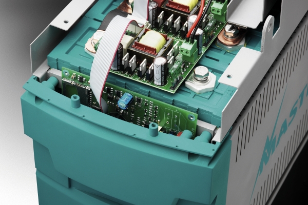
High-capacity inductive charge pumps on top the cells inside a Mastervolt MLI lithium battery pack.
The photo shows a 30A blade fuse and the transformer performing the coupling between cells at different voltages on the top circuit board. In front of the transformer (yellow and red), we have 4 MOSFET transistors (typically in a push-pull arrangement) flanked by two electrolytic “tank” capacitors. The transistors switch the current going to the transformer and the capacitors provide the peak of the current. Switching high currents into inductive loads like transformers at high-frequencies is hard on electronics. The most likely failure mode is one of the MOSFETs failing short from stresses, at which point a second transistor might then get destroyed by current overload before the fuse blows.
Note the control board installed vertically on the front and the ribbon cable to control the balancers. More electrolytic capacitors (blue and cylindrical) there.
Passive Balancing
Passive balancing can be used with top or bottom-balanced packs and its aim is maintaining cell balance either at the top or bottom by shunting some current over any cells registering an excessive state of charge compared to the others. As the battery banks of interest to us here are basically always top-balanced, we will consider shunt-balancing at the top.
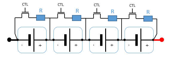
A 4-cell battery with cell shunt balancers. The control signal operates each transistor like a switch.
Shunting involves connecting a resistor across the cell terminals: if the cell is charging, some of the charging current will flow through the resistor instead of through the cell and the cell will be charging at a reduced rate. If the cell is not charging, then the resistor simply contributes to producing a discharge current for that cell only. The amount of current flowing through the shunt is the ratio between the cell voltage Vcell and the resistance R of the shunt circuit. Either way, a resistive balancer operates by “wasting” some energy. The amount of power the balancer needs to dissipate as heat is P = Vcell 2/ R.

Shunt balancer during charging. The cell current Icell is reduced by the amount of the shunt current Ishunt and becomes smaller than the battery charging current.

Shunt balancer in discharge. The cell current Icell is increased by the amount of the shunt current Ishunt and becomes greater than the battery discharge current.
Smart Shunt Balancing
Ideally, a shunt balancer should waste exactly the amount of charge required to bring any high cells down to the level of the others and therefore restore balance. In this case, shunting can happen during discharge and at normal operating voltages. Practically, determining how much energy this represents cell-by-cell is a non-trivial task that first requires knowing the state of charge of each cell at the end of a full charging cycle. Then it becomes possible to selectively deplete any cell requiring it by the precise amount needed to achieve balance. A computer-controlled centralised BMS with a current sensor is required to do this. This type of balancing only needs to occur occasionally and only needs to perform very small corrections. The shunting currents can be very small because once the magnitude of the correction has been calculated, the adjustments themselves can be done over hours or days while the bank is operating normally. Factory-engineered EV battery packs typically operate this way.
Example:
As we were finishing to charge a pack, we determined that we need to perform a balance adjustment of -1Ah on a specific cell. The cell voltage is now Vcell = 3.35V and the shunt has a resistance of R = 10Ω. The shunt current is equal to Ishunt = 3.35V / 10Ω = 0.335A and the amount of shunting time required to deplete 1Ah is t = 1Ah / 0.335A = 3 hours.
However, if the cell voltage drops during this period, the shunting time will be extended. The BMS needs to continuously track and accumulate the amount of energy shunted and every cell effectively has its own capacity monitor embedded in the BMS.
The shunt would dissipate P = 3.35V x 3.35V / 10Ω = 1.12W in heat, which is a very modest value.
Voltage-Based Shunting
Voltage-based shunting is a crude shortcut sometimes used with cheap equipment and is commonly found on BMS systems built around cell boards. Shunting begins whenever the cell voltage exceeds a threshold. This strategy can work if the shunting voltage is only ever reached at low currents and the cells are near-fully charged each time. It can work for charging DIY EVs overnight at C/10 using CC/CV chargers. Charging at high currents with alternators on boats results in the cell voltages rising too early, because of the parasitic effect of the internal resistance of the cells. At this point, the shunts engage and operate not only based on the state of charge of each cell, but mainly on its R x I voltage drop. Cells with higher internal resistance get shunted and receive less current for no valid reason. This typically results in upsetting balance. If charging continues until the current tapers down to a very low value, the shunts may find enough time to correct for the upset they caused earlier. On boats, we often shut the engine down before this has happened and start discharging again and the shunting cell boards just mess up the bank.
Voltage-based shunt balancers commonly create significant heat, because there is very little time to fix up cell balance at the top before charging terminates and they need to handle a lot of current compared to a calculated shunting strategy. In practice, shunting cell boards cause so much havoc that their threshold voltage is usually set high enough to make them virtually useless. Their main pitfall is that they have no idea of what the battery current is doing and they shunt while the current is still high.
For doing the same work as above, a shunt balancing cell board with a capacity of Ishunt = 2A starting to operate at Vcell = 3.6V would produce P = 3.6V x 2A = 7.2W of heat for t = 1Ah / 2A = 30 minutes. The cell voltage would also need to be held at 3.6V for that duration by the charging system, which means overcharging.
In other words, a 2A-rated shunt isn’t enough to do the job, because it takes too long.
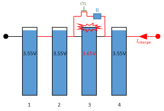
A voltage-driven shunt balancer trying to balance a high cell (3) out needs to carry all of the charging current to prevent the high cell from getting further stressed by overcharging. Balancing needs to continue until cells 1, 2 and 4 have caught up with cell 3.
Voltage-based shunts are voltage limiters with a limited current capacity, i.e. their rating. In order for them to work properly, the charging source also needs to cooperate: if the charger supplies more current than the shunts can carry, then some current must go through the cell and its voltage will keep increasing. Also, in order to balance the pack, all the other cells eventually need to be taken as high as the overcharged cell, which takes a long time and is undesirable. Voltage-driven shunting is a generally a poor strategy unless it can operate at lower voltages with a charging regime controlled to make it work. It is never the case when it is just blindly thrown into a system.
Shunt Balancer Reliability
A passive (resistive) balancer can also fail, of course, in one of two ways: open-circuit, and then it simply can’t operate any more, or fail short and then it can’t be stopped. The first failure mode is less likely and could go unnoticed for a long time. The second failure mode is the harmful one as it would cause the affected cell to get discharged uncontrollably to destruction. There is much hype around about “cell balancers destroying banks” and very little in the way of supporting cases once all the cases of brand new faulty cell boards are discounted. A passive shunt balancer operates at cell voltage only and switches a resistive load, i.e. no spikes. This means virtually no stress on the switching transistor and it makes it immensely reliable compared to active balancing circuits.
Other Battery Management Functions
Reporting the state of charge of the battery is a BMS function sometimes present. A BMS with a chemistry-specific SOC algorithm will massively outperform any ordinary battery monitor in data accuracy and reliability.
Disabling charging in excessively low temperatures or battery temperature control are management functions sometimes available on upper end units. A BMS should ideally direct charging as it is the only piece of equipment in the system actually capable of determining what the battery needs.
BMS Topology Considerations
BMS solutions come in two main flavours: either distributed or centralised. The difference would not matter much if the functionality was identical, but distributed BMS systems have slipped towards the cheap and nasty end of the spectrum in recent years.
Distributed BMS Architectures
Distributed BMS systems typically have the advantage of being scalable over a large and variable numbers of cells in series. These systems use one “cell board” per parallel cell group and usually some kind of head unit to implement the control functions. In order to retrieve the information pertaining to each cell, a communication bus linking all the cell boards is necessary. This increases the complexity and cost of the cell boards and the communication loop can be seen as somewhat vulnerable: this is not automatically true and cell boards themselves are commonly vulnerable due to their lack of physical protection, especially in marine systems. Regardless, this was “addressed” by some designers focused on the low end of the market by using a simple current loop over a single wire, starting from the master board, passing through every cell boards, and returning to the master. It is no longer possible to transport individual cell information, so the loop just carries information about one or two conditions typically, like over-voltage/under-voltage. The master can see an alarm condition, but can’t identify the cell it is originating from. It makes battery management impossible, but protection without any diagnostics can certainly be obtained this way.
As most of these “one wire loop” systems are first and foremost designed for lowest engineering and production cost to the vendor, many other aspects tend to leave much to be desired. Close attention must also be paid to the protection limits implemented, because the clear intent is often allowing drop-in lithium battery replacements on automotive installations where battery-damaging (but not dangerous) charging voltages must not trip the “BMS” and cause grief to the installer.
Some early distributed BMS solutions implemented digital communications across all the cells and were scalable up to fairly high voltage pack configurations, typical of EV systems. This can be quite good, but it is more complex to design than a centralised BMS. In recent years, distributed solutions have drifted towards the bottom end of the scale.
Centralised BMS Architecture
On a centralised BMS, voltage sensing wires run from each cell to the module, as well as wiring for the cell temperature sensors. This wiring needs to be arranged neatly, but it is easy to protect. On marine installations with 4 or 8 (groups of) cells, it is always straightforward. If battery management is the objective, then the BMS must also have access to battery current information through a suitable sensor. Depending on what the objective of the management algorithm is, the BMS may need access to the installation load current as well as the battery current, or currents through the charging and discharging paths separately.
A centralised BMS has access to every piece of battery information in one place and at any time: this is necessary for implementing many management strategies, including and especially smart cell balancing. It becomes possible to track capacity cell-by-cell, track cell internal resistance, predict time-to-empty, issue charging parameters, manage charging sources and loads and much more.
Centralised BMS modules tend to include more engineering effort, especially on the firmware side. A vendor interested in marketing BMS for maximum profits immediately looks in the direction of a distributed system with cell boards and an analogue loop, because it can easily adapt to any number of cells; a centralised unit can only offer a predetermined number of inputs for cell voltage measurement and will only fit installations within these limits.
BMS Reliability and Failure Modes
From a reliability point of view, a BMS is just an electronic circuit with external connections. It can fail in two ways: internally, or due to an external event reaching it through its connections.
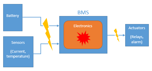
The reliability of a battery management system (BMS) can be challenged by design and construction factors (internal) as well as external events such as voltage spikes or short-circuits outside.
Internal BMS Failure
An internal, or intrinsic failure, is a failure “for no apparent reason”. Ageing of the components, component defect, manufacturing defect can all lead to an internal failure. Quality of the parts and construction have a role to play, but also design: components like electrolytic capacitors have a finite life, which gets shorter at high temperatures. After 10-15 years, most electrolytic capacitors aren’t looking too good in general. In a device like a BMS, they can be easy to avoid altogether and ceramic capacitors can be used instead, with a near unlimited life expectancy. They may just cost a little more. The maximum voltage rating of the parts used also matters a great deal: 16V-rated components exposed to battery voltage in an automotive-like system have almost no margin for surviving voltage transients.
Electronic devices are most likely to fail “for no reason” when they are either very new or very old
Component and manufacturing defects tend to come out at the start, while ageing effects appear at the far end. The ageing limit can be pushed so far back by design and component selection that it can move past obsolescence and become irrelevant: the Voyager space probes are still sending back information after 40 years.
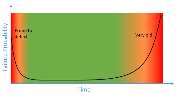
The probability of failure of electronic equipment is highest immediately following manufacturing due to the risk of defect and at the end of the product life due to ageing.
The failure probability curve of electronic hardware has a characteristic U-shape. Quality control and factory testing at the start are intended to take out most of the bad samples and prevent them from reaching the market. From the user’s point of view, the failure risk keeps decaying immediately after purchase and reaches a low level that remains somewhat constant over most of the product’s life. This level is very much a function of the quality of the product.
The prospective life of well-managed marine LiFePO4 banks already appears to be in excess of 10 years (as of 2017), based on data from early installations, and this figure keeps increasing all the time. As a BMS should logically outlast the cells it is protecting, this is placing increasing demands on the long-term reliability of the units. Even though we don’t yet see this into the BMS market, it is starting to make more and more sense to design for 20 years of operation now.
BMS Failure from External Event
On one side, a BMS measures small signals and, on the other, it actuates remote devices. These connections and the associated wiring can pick up transient voltages, RF energy or be exposed to unfortunate events caused by the installer or user. How resilient the BMS is to such events at its terminals depends on how much protection was built into its design.
Devices that include protections at their terminals are sometimes referred to as being “hardened”, like industrial-grade control equipment. Hardening electronic circuitry means adding components that serve no functional purpose and may never actually do anything over the life of the device. They exist as an insurance policy, and should an abnormal event take place one day, they can prevent damage to the device. An industrially-hardened circuit can include a lot of such additional components for protection, they take board space and they add to cost without contributing anything to functionality. For this reason, they are the first ones to be found “missing”.
A particularly vulnerable part of BMS modules is the outputs driving the battery disconnectors. Relay coils are inductive in nature and produce a current surge on energisation and a reverse voltage spike upon de-energisation. These are hard on the MOSFET switching transistors handling the current. When such a MOSFET fails, 99% of the time it turns itself into a short-circuit. It is very bad news for a lot of BMS designs:
The BMS is holding a normally-open battery disconnector closed. It looks fail-safe: lose the power and the contactor releases, disconnecting the battery. One day, the voltage transients caused by switching the relay coil finally manage to kill the transistor, which can’t be turned off any more. If the contactor is supposed to be closed, the installation has power and the failure is both hidden and undetectable, but the system has no protection any more. This is the worst kind of failure mode.
If the BMS uses latching relays instead, then a transistor failure becomes detectable, because the coils should never be energised under normal circumstances. However, should the BMS suddenly “stop” functioning, it may leave the battery connected indefinitely (in both configurations, by the way). This can be addressed too, but the intent here is not to delve deeply into electronic engineering. This type of thinking and analysis is part of failure mode analysis. It needs to be performed by system designers both at component and installation levels.
The designer of a BMS can go to great lengths to mitigate or eliminate these risks and design up to a standard, or instead ignore them and design down to a cost, and the product may have no more and no less functionality for the user and yet be vastly different in suitability. Quality does matter in relation with the application and marine applications include situations where high reliability matters, and others where people or large assets can be at risk.
Last, but not least, a BMS module is just one component in the system and its role is ensuring that no single failure can result in a hazardous situation. The designer of the battery bank and associated electrical system should ensure that his installation does not depend on the BMS to operate safely, but instead relies on the BMS to protect itself if something goes wrong. This way, two cascaded failures need to take place before risks develop. Meanwhile, a single failure must be both visible and detectable, or it will go unnoticed until a second one follows and causes some disaster big or small, but usually costly!
General Guidelines for BMS Installation
Protecting the bank is an essential part of installing it on board. The details of the installation of a BMS are specific to the solution retained, but it must always involve establishing dedicated connections for sensing the cell voltages and should also involve adding temperature sensors to the cells.
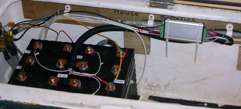
This 2P4S 400Ah lithium battery bank during installation on a sailing catamaran is occupying a fraction of the space previously allocated to the deep-cycle lead-acid batteries. The owner must still clamp and secure the cells. The cell voltage sensing and temperature sensors wiring is going to a Gen 1 Nordkyn BMS module controlling remote latching disconnector relays in the electrical panel several metres away.
The best location for the BMS module is generally close to the battery, so the length of the voltage sensing wiring is minimised. Keeping this wiring short makes it less susceptible to pick up electromagnetic disturbances. Keeping the cell-sensing wiring into the battery compartment also eliminates considerations around fusing that wiring, a questionable idea as it negatively affects reliability.
The DC disconnectors associated with the BMS can be relocated to meet wiring constraints. It is sometimes simpler to run a feeder cable from the battery to the distribution panel and split the system into a charge bus and a load bus over disconnectors at the panel, rather than inside the battery compartment. In some circumstances, an argument can be built for installing the BMS and disconnectors literally into the battery pack with all cell terminals inaccessible when there are any risks of third parties interfering with the battery. This type of construction makes bypassing the battery protection layer impossible without first resorting to tools and some dismantling.
Last Words
Over the last two years or so, I received a number requests to write this article. I resisted and deferred because I have been using my own BMS modules, but the focus here is on the technology.
This article now logically complements the construction of lithium battery banks and all the changes required in the battery compartment for transitioning from a lead-acid battery to a protected and operable lithium iron phosphate battery have been covered. Over a year ago already now, I was writing about the all-important aspect of redesigning the electrical system to operate with a lithium battery and a BMS and this now just leaves the interesting subject of charge control and charging the cells on board. Lithium batteries require full system integration to offer the best performance and longest life, something even high-cost commercial solutions have commonly overlooked. After a while, some of these vendors have had to face the longer-term consequences and cost associated with their engineering shortcuts that sacrificed battery life and pulled out of the market.
References:
[1] DNV GL Guideline for Large Maritime Battery Systems, DNV GL – 10/03/2014 No. 2013-1632, Rev. V1.0
Dear Eric,
Thank you for this detailed information. I am an experienced sailor, who will return back to sea when my youngest goes to college in 4 years. I circumnavigated on wet cells, and am extremely interested in the LiFEPo4 changes to way we manage our power.
Q1. I saw in one of your article stating that you should keep the temp below 25C, but in the equatorial tropics, the day temp is about 30C, and the night does not drop the temp much. In wet batteries as long as you are watering the batteries you can overcome the ambient temp, how would you do that in a LiFePo4 system. It also means that you cannot have you battery location in the engine room, which was not obvious till now.
Dear Jonathan,
In the Tropics, you can’t realistically expect temperatures below the sea temperature, so up to 28degC in places. Having the battery low in the hull is the best you can do. It will age more quickly than it would at 20degC, but I would still expect it to last a rather long time.
Having them in the engine room would be senseless, as the temperature goes over 50degC and this would cause rapid degradation. It is especially bad on launches as they motor for long periods, but… many “cruising” yachts also motor a lot of the time for reasons that we will carefully leave aside here…
The aging mechanism causes the internal resistance of the cells to increase, the capacity only appears reduced if you try to get too much current from a degraded battery. In the end you might find that the voltage sags abnormally if you put a heavy load on the bank and then it will be a hint that it is reaching the end of its life. We tend to operate at low currents, so no one really knows how long one of these battery can last until it can’t do that any more.
The best answer for the tropics might be to keep the battery small, because charging is never really an issue. In all “sensible” sailing applications, I tend to think that anything more than 200Ah @ 12V achieves nothing at all (except converting cash into useless lithium). This way, if the battery proved to have a somewhat disappointing life against the 10+ years we are increasingly coming to expect now, you would have at least minimised its capital cost and maximised its utilisation.
Best regards,
Eric
Hi Eric
Thank you for the thorough explanation. I can only guess the time you took to do this.
You have not listed your Gen 1 Nordkyn BMS in your products for sale. (I only can see a listing for an alternator controller.) Are you going to sell this?
( I can only count 6 cells in the picture of the 2p4s 400ah battery above. I might have missed something there)
Thanks again
David
David,
I try to write one new article each year these days… they do take a while to write indeed!
I have been trying to move past that BMS shown into the pictures for production reasons, this is the reason why I haven’t got it listed as a product. I have another model on the bench that is more suited to manufacturing, as well as the prototype of a more complex unit I have been experimenting with.
It shouldn’t be too far away now.
There are 8 cells in the picture, look at the number of bolts at the cell connections.
Thanks and kind regards,
Eric
Hi Eric,
In regards to protecting the lithium batteries from overcharge. Why not have a voltage controlled relay on the wires coming to the solar charge controller? Also if an alternator has a maximum output of 14.4 volts, it will never get high enough volts to overcharge the Lithium batteries?
Regards, Ryan
Ryan,
Any voltage above 13.6V is enough to overcharge four LiFePO4 cells in series, see https://nordkyndesign.com/practical-characteristics-of-lithium-iron-phosphate-battery-cells/ and look up “The Relation Between End-of-Charge Voltage and State of Charge”. It is a complete misconception that the maximum state of charge is related to the charging voltage. It is not.
14.4V is not only high enough to overcharge the cells, but it would also take them into a region where cell balance is extremely twitchy and very small differences in state of charge result in large voltage variations. Battery charging on board yachts is not a well-controlled and consistent process and the charging voltage is not smooth filtered DC power from all sources. Overcharging the cells invariably leads to their destruction as some cells end up going way over-voltage.
The charge must always be terminated.
Regards,
Eric
Thanks for your very detailed articles. I have been thinking about this and have also been chatting with my old friend, Mikael Nordman who has commented elsewhere on your pages.
Like Mikael am I a great believer in simplicity so his idea of having a battery bank for the boat that you top-balance every winter has a certain appeal. Now like Mikael am I an EE so this is what I propose:
No active battery management, ie balancing, but battery protection. The battery is connected through a fuse and then a latching mosfet relay with an initial power-on state of OFF. The relay is controlled by two pushbuttons, on and off and by a circuit that measures the voltage of each individual cell. If the voltage of any cell rises above Vhi, say 4V or Vlow, say 2.5V, the battery is disconnected immediately. The voltages is something we could discuss. If the battery manufacturer claims 4V and 2.5 volts, then perhaps 3.9 and 2.6 would be better.
I have a prototype running. It is basically some precision opamps and comparators. The current consumption is less than 1mA, which should be far lower than the ordinary self-discharge.
If this turns out OK then I will open-source the design.
Comments?
Hello Anders,
The issue with what you are proposing is that not damaging a lithium battery goes beyond just keeping the cell voltages within a range, especially a range as wide as what you are suggesting and derived from specifications that were largely abandoned some 10 years ago, for very good reasons.
There is a considerable difference between “simple” and “simplistic” and implementing what you are describing here would do nothing to safeguard the battery from overcharging and destruction. At best, it would just protect you from a fire. Such a design would in fact be inferior to what you find within packaged lithium batteries advertised to be dropped into lead-acid charging systems without alterations. It would also be no different or inferior to many of the junk-grade BMS solutions you can already buy on the market for record low prices.
In order to deal with a lithium battery effectively, you need to have an idea of its state of charge and make decisions which take it into account. This is why charging, battery management and protection are ultimately a job for a microcontroller and it needs to know not only about all the cell voltages, but also the battery current, its variations over time, the charging history of the battery and the cell temperatures.
Of course you could rebalance your cells manually once a year if you feel like it. Replacing some circuitry by manual intervention is a personal choice, but, in the bigger picture, it is hardly a smart idea. We want battery systems that take care of themselves and perform throughout their life without requiring specialist knowledge and intervention, not some energy storage contraptions that requires babysitting not to go wrong.
People have tried to cut corners with lithium battery cells for a decade now and it has always worked exactly until the bank got destroyed. Overall, practices have gradually improved with better understanding of the fundamentals. There is no need to go back to the beginning now. These systems will reach full maturity with the seamless integration of protection, management and charge control.
Let me add (in addition to what I just wrote), that what I am suggesting is a circuitry for battery protection, not management. This is also for my own use or for someone with similar requirements, which are:
– Capacity approx 100Ah
– Drain is mainly fridge, navigation and lights, say less than 10A peak
– Charged from a solar charger designed for LFPs and possibly from shore at max 0.1C, again an LFP charger.
– No charging from the engine generator (which removes a lot of possible, dangerous, scenarios)
There will also be an MPU that reads individual cell voltages and count coloumbs.
The initial setup has now been in use over the summer. There is no active balancing of the cells. They were top-balanced to 3.5V in parallell in the spring, then cells were connected in series and loaded until 12.8V (3.2/cell). Autumn 2022. When measuring individual voltages (HP 3456A DMM) I got. 1: 3,3334V, 2: 3,3332V, 3: 3,3328, 4: 3,3332V.
Ie, cells (Winston) are within 0.6mV after one summer’s use.
They were charged from Solar only and used to feed fridge, navigation (VHF, GPS) and lights.
I noticed that the drop from the MPPT charger (2A) to the battery was significant and as there is no way to have aa separate sense wire, I will relocate the charger closer to the battery. The drop was enough to stop the battery from charging fully.
But the voltage range I am suggesting was just an initial suggestion, based on the data from one particular battery cell maufacturer. I agree that it is a very wide range and it could very well be made smaller. The general idea was for it to be a supervisory circuit that would be extremely reliable and to act as a last resort cutoff. It would then be augmented by a MPU that reads data from a coloumb counter and the individual cell voltages to present an accurate SOC.
Such a circuit only protects the battery from a catastrophic failure in the charge control infrastructure where the voltage would otherwise keep rising uncontrollably, it doesn’t prevent destroying the battery more slowly by overcharging it and it won’t do anything if something starts getting hot in charge or discharge. Furthermore, if it did disconnect, it would leave your “bad” charging source directly connected to your loads and fry them, which is discussed at some length in another article about electrical design. Why bother with something that is not adequate?
Virtually all “lithium” charge controllers can only sense their own charge current – not the actual battery current – so they basically can’t terminate the charge correctly because they can’t identify how much of the current is going to the loads. There is no solution to be found by trying to split and dissociate matters.
If you are going to have a MCU in the system anyway, then use it and build an integrated system. The code won’t be simple for sure, but once it is in a black box, the system can become very simple. Much simpler than the mess that always arise from trying to interconnect disjoint components that are not fit for the task.
Eric,
Great site.
I am in the early stages of assembling by bank of cells. I haven’t as yet sourced the cell interlinks, and am struggling with the copper vs aluminium options. You appear to favour aluminium in the absence of commercially available copper links.
Like Jason P in his comments of 15th January, I am concerned at the effects that a solid bar may have on the cell terminals as opposed to the layered approach with the upward curve in terms of vibration and thermal expansion.
I would be grateful for your thoughts on the matter.
Richard,
Many copper links are solid and way too thick to offer any mechanical advantage regarding expansion/contraction. The bottom line is that a LFP house bank runs cold, i.e. within a few degrees of ambient in the most extreme circumstances and nothing happens.
You can run 6mm thick aluminium flat bars across the cell terminals and it is fine. Just make sure your pack is clamped and assembled first and use slightly oversized holes in the busbars (or elongate them a little with a file) so all the bolts go in freely. It is not more complicated than that.
Kind regards,
Eric
Hello Eric,
Great article. I was hoping though that you would also cover how to protect the batteries physically. I have a wood/epoxy composite boat that I want to use an electric motor with. An LiFePO4 battery has several desirable attributes (lighter, more stable continuous voltage etc) so I would like to use an off the shelf 12V LiFePO4 120Ah battery with built-in BMS and a charger suited to LiFePO4. However, how should the battery be physically protected and stowed?
While protection from climate (hot days, cold days) is one consideration, so too is the matter of seawater ingress.
A regular battery box, I assume (it has vents built-in for example), will always let some seawater in. I have read that seawater (and freshwater too for that matter) is bad for LiFePO4 batteries and can release bad things e.g. HF gas. There must be a way to physically protect a LiFePO4 battery, but what to do?
I would appreciate some suggestions on what can be done to physically protect an LiFePO4 battery.
Thanks in advance.
Hello Tony,
Common sense applies here, I suppose. No battery should be immersed in water, shaken or dropped from a great height. Fasten it in a dry location, away from unfavourable temperatures and where accelerations are modest, i.e. not in the bow. Protecting the terminals against short-circuits with a sheet of plastic can make sense, especially on top of the larger battery packs assembled from prismatic cells.
Lithium batteries produce no gases at all, so venting is not a consideration. They are also fully sealed with a pressure-relief cap, so not much should happen even if they become submerged. They will just discharge, decompose some seawater in the process and corrode their terminals. Immersion in salt water is an acceptance test carried out by some manufacturers like CALB by the way. A battery with built-in electronics will likely be ruined if immersed… common sense again.
I would just note that if the cells have aluminium casings, then there is a risk of corrosion over time if they are exposed to sea water. The cells with plastic casings were inert and arguably much better suited to the marine environment.
Kind regards,
Eric
I have winston cells. A friend machined aluminium bits that would fit into the groooves on the side, then two aluminium plates at each end and stainless threaded studs to keep it together. The grooves stop the cells from sliding out when not tightened. The whole contraption sits in a space under one bunk. Two 20x20mm square stainless profiles have a tappet in one end that goes into a hole in the bulkhead and the other end is secured to the bunk bottom with bolts. That way it would probably stay in place even if knocked down, even if that is highly unlikely in the Baltic
I wish I could post pictures here.
Hello Eric,
Thank you very much that you sharing so much information and knowledge about LiFePO4 batteries. I would like to ask you a question about clamping the cells together. I saw that you use threaded rods and plywood to clamp cells. How much force you apply to tighten the rods (Nm)
and at what SOC?
Kind regards
Hello Milen,
The older cells with plastic casings need to be clamped very tightly, but I have never measured the pressure used. The torque on the nuts at the ends of the threaded rods would depend on the pitch of the thread. I thought about measuring the elongation of the threaded rods and calculating the tension from there, but I never got there.
The newer cells with aluminium casings are different and only need to be clamped enough to be held in place, but electrical insulation must be installed between the cells.
The state of charge doesn’t matter when you clamp LiFePO4 cells, the chemistry is very stable dimensionally.
Kind regards,
Eric
Thanks for the fast reply. I’m using CALB CA100 cells, and wonder how much force to apply to it but no damaged it.
Milen,
You need to clamp these cells. If your end plates are very rigid, you can’t realistically damage the cells. Just clamp them very tight. The casings should not deform.
Kind regards,
Eric