
Last Updated on 24 June 2021 by Eric Bretscher
Starting Point
I had hauled out the sloop Nordkyn for its less-than-annual bottom paint job. It was November, that year had been long, and so was getting the thin stringy weed clinging to the hull. In this condition, the boat is unusable. I was determined to make the effort last and so I generously sprayed the new antifouling in two thick coats. A tinge of irritation showed when, three weeks later, I noticed light green slime already forming on the rudder blade, and six weeks later this had turned into thick heavy slime over the entire hull – in the cold waters of Southern New Zealand. Nothing that the odd dash at 18 knots didn’t remediate when I sailed off in January, but this of course only postponed the disaster. By March, in warmer waters, I was diving underneath the hull and scraping off barnacles in the hundreds.
At this point, a short discussion was up with the paint company, and I politely suggested they had sold me paint from a faulty batch. “Certainly not”, responded their sales manager, an individual who has earned himself here a well-deserved reputation for always blaming the customer, “you simply didn’t apply enough product for it to be effective”. Not enough paint to last three weeks, as if more of a useless product was going to deliver an enhanced result. In fact, I had applied 50% more paint than the previous year. So I objected, only to be told this time that the water was “special” this year, “not our fault”, but primarily around my boat, because others seemed to cope with the special water quite normally. “Aluminium-compatible antifoulings are naturally less effective, there is nothing wrong with it”. As we were about to debate the concept of fitness for purpose in a venue I was going to kindly organise, they shipped me a very reasonable amount of replacement product. Fine.
Still, it took a while to get there, the new paint didn’t apply itself onto the bottom and I had the pleasure of hauling out again. During these lengthy proceedings, the idea of installing an ultrasonic antifouling system for preventing organisms from attaching too readily found a new incentive. These systems are priced like the rest of the marine electronic gadgetry and there seemed to be no clear verdict out about their effectiveness. They always seemed most effective from the manufacturer’s point of view basically. Aluminium hulls however appeared to show consistently positive results. In these circumstances, I looked at what I had to lose in relation with the cost of painting a 43-footer: certainly not much if I built my own system. The project had therefore literally “started in anger”.
Ultrasonic Antifouling: Principle and Limitations
The theory behind ultrasonic antifouling systems is that the vibration induced in the hull plating, and maybe the surrounding water, disrupts cellular growth in organisms trying to attach and develop against the hull. It creates an adverse environment. What these systems don’t do is produce cavitation and a “layer of micro-bubbles” against the hull as some inept claims suggest. That would require the kind of power found in an ultrasonic cleaning tank, 0.5-0.6W/cm2, or a mere 180kW for a vessel like mine, and it would probably strip the antifouling off in a matter of minutes! Interesting scientific research supporting the use of ultrasonic energy to keep marine hulls clean was published in 2016 [1].
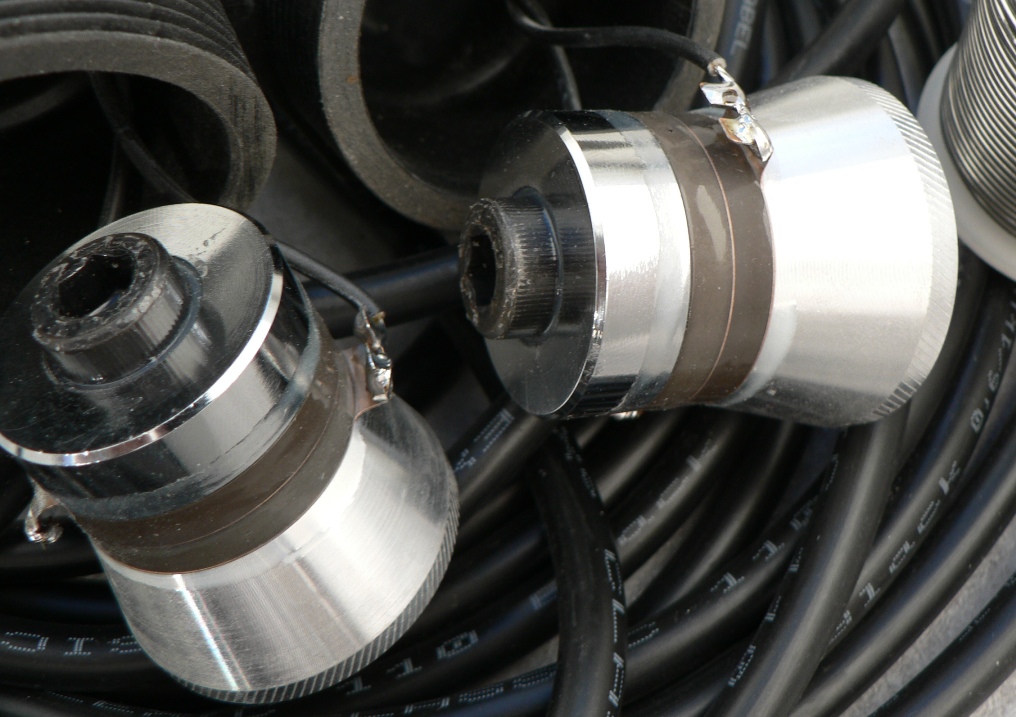
Ultrasonic transducers before encapsulation. Note the two ceramic discs and the compression bolt.
The vibration is induced into the hull using a piezoelectric transducer, at the heart of which are ceramic elements sandwiched between electrodes. When a voltage is applied to the electrodes, an electric field forms through the ceramic, which either expands or contracts depending on the polarity. An ultrasonic transducer attached to a hull produces a longitudinal wave on the axis of the device, which passes through the thickness of the hull and dissipates into the water, as well as a guided shear wave that travels radially away from the transducer. This shear wave is the one that can propagate throughout the hull and installing the transducers on a section of unsupported plating maximises it.
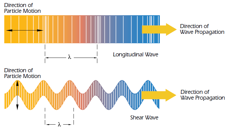
Propagation of longitudinal and shear ultrasonic waves in a material (Source: Olympus NDT, “Ultrasonic Transducer Technical Notes”).
The material and construction of the hull has a significant impact on the ability of the shear wave to travel away from its source, which is enough to explain the variability experienced in the results. Aluminium, being light and extremely rigid, is notoriously good at transmitting sound; steel is excellent too. In these materials, the propagation velocity of the shear wave exceeds 3000m/s [2]. Solid fibreglass normally gives good results too. Timber, on the other hand, absorbs vibrations. Cored hulls are usually deemed unsuitable, unless maybe the core material is removed to install the transducer against the outer skin, but I have no experience with them.
Ultrasonic transducers are designed for a specific resonant frequency and they don’t operate well at all frequencies, but they can resonate to some extent at frequencies other than their design frequency [3]. Research suggests that organisms also react differently with regard to frequency and the standard approach in this application appears to be sweeping over a relatively broad spectrum of frequencies to maximise the chances of success, both in terms of transducer performance and impact on growth.
Development
A design for a single-transducer ultrasonic antifouling driver, engineered by Leo Simpson and John Clarke, had been published in the September 2010 issue of Silicon Chip Magazine, #264. Shortly after, it was commercialised in the form of a kit by Jaycar in Australia and New Zealand at an attractive price when compared to ready-made commercial systems. I had heard some good first-hand reports about it. At 13 metres, Nordkyn would require two transducers however and, rather than installing two kits, I decided to build my own modified version of the Silicon Chip design that would be able to drive two transducers instead of one. It appeared easy enough and much more interesting.
Driver Board
The piezoelectric transducers are capacitive loads driven at voltages of a few hundred volts through high-frequency step-up power transformers in a very conventional arrangement [4]. The transformer winding, the cable and the capacitive transducer form a resonant circuit and driving two transducers required a whole new second power stage. Some of the components used in 2010 were no longer in production, I wished to improve some aspects and, altogether, this led to building similar, but different electronics. Still, I expected little trouble as the starting point was a working design, but the circuit handles quite high peak power levels and this assumption didn’t prove entirely correct. When the time came, I decided to test a single channel first: it is not every day that one can freely opt out of 50% of a potential disaster. The circuit failed promptly and the fuse protested with an orange flash, but this was nothing a few alterations couldn’t overcome.
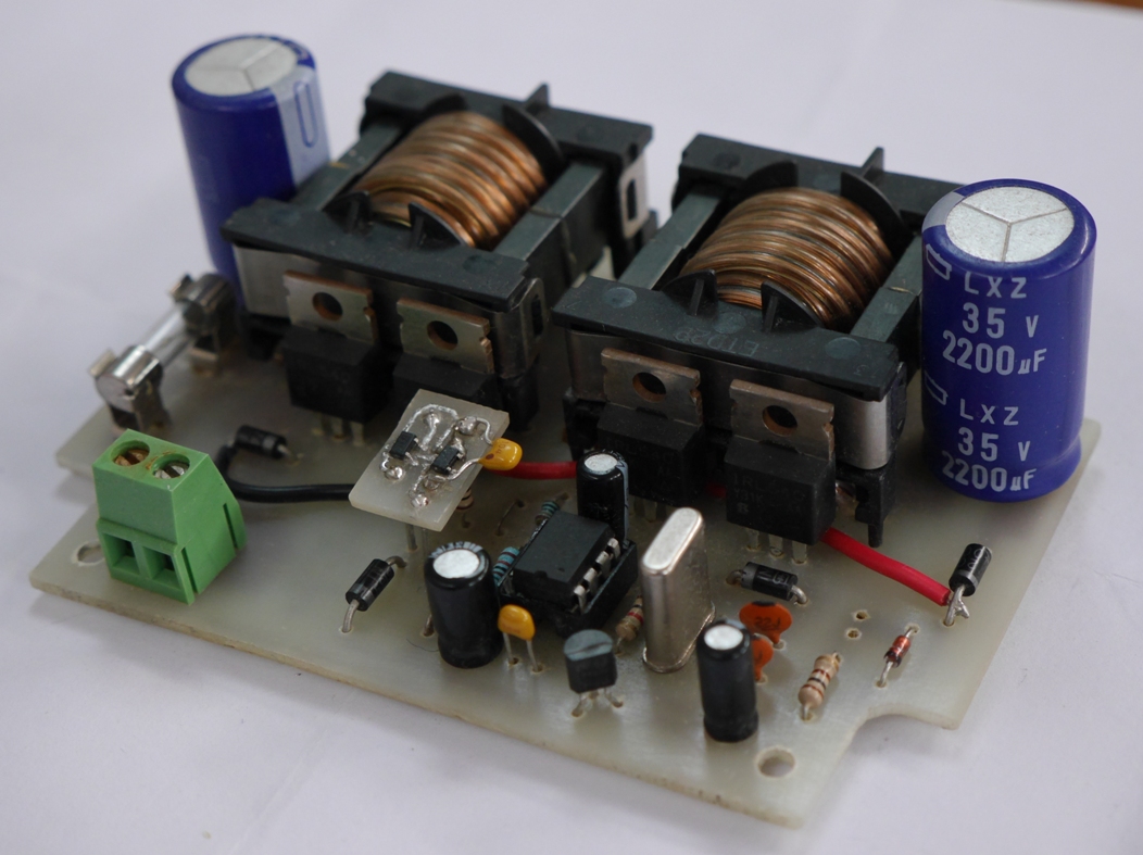
The prototype of the dual-channel ultrasonic antifouling driver in its final state, after a few initial alterations and then three-and-a-half years of continuous service.
It has now operated continuously for over 3 ½ years at the time of writing (mid-2018) without any intervention, so I have decided that it must be robust and reliable.
Transducers
One aspect I was very unhappy with when I reviewed the Silicon Chip article was the presence of soft, rubbery potting compound between the ultrasonic transducer and the hull. Of course, some of the vibration will propagate through, but there is nothing like direct contact between hard incompressible materials to transmit sound. A large amount of efficiency would almost certainly be lost this way. The transducers used in this type of application are primarily manufactured for ultrasonic cleaning machines; in this kind of equipment, they are epoxy-bonded to the outside of the tank wall and literally vibrate with the tank. Gluing the transducers to the hull is perfectly possible and would even be desirable. At the time, I elected to install them in a less permanent way, as the whole venture was very much an experiment.
Some original Jaycar systems showed much improved performance when the potting compound was scraped off the face of the transducer and replaced with a piece of fiberglass board epoxy-glued into place.
As the voltage at the transducer terminals can exceed 800V at times, electrical insulation is essential for safety. On a boat, the transducers are also by definition in the bilge and they need to be completely sealed from moisture. I used synthetic plumbing fittings and polyurethane resin to encapsulate the transducers, similarly to what the article described, but I first bonded a piece of hard fibreglass/epoxy board to the face of the transducer to insulate it and made sure it would come into direct contact with the hull.
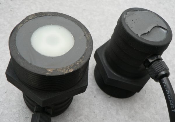
Two ultrasonic cleaning transducers encapsulated in plastic plumbing fittings and polyurethane resin. Note the hard fiberglass face on the bottom of the unit on the left. It protrudes slightly from the base of the housing and sits flat against the hull.
I located the transducers by first splitting the underwater hull surface into two equal halves and then determining the approximate geometric centre of each area. This gave roughly 15m2 of hull plating per transducer with the keel and rudder in addition to that. I made sure the transducers were installed in the middle of a hull panel, as far away as possible from the frames and other stiffeners. This prompted mounting each transducer off-centre: the front one is forward of the mast and to starboard and the aft one is behind the engine and to port.

A threaded flange was epoxy-bonded to the hull plating away from the stiffeners and the transducers is then screwed tightly into place.
Did It Work?
Yes. I built the prototype presented above in the second half of 2014 and commissioned it in early 2015. In New Zealand waters, we get little creatures we refer to as snapping shrimps because of the sharp crackling noises they make as they crawl under the hull. While they initially dislike the taste of fresh antifouling and always wash off with boat speed, it doesn’t take them long to get comfortable once the boat stops and the music starts. When I powered up the ultrasonic system, their noise started fading away and, after a while, the hull was much quieter, other than for the faint clicking sounds produced by the transducers. It suggested that the vibration was indeed propagating throughout the underwater hull and this appeared positive.
Hard Growth
The system has now operated continuously for 3½ years and it essentially eliminated all of the hard growth on the hull: no more barnacles and coral-like formations. Barnacles migrate through the water as tiny larvae, attach to the hull and then start growing a shell. When the water is choppy, I can sometimes see some larvae beneath the waterline; a few days later they are gone. They simply can’t live and develop against the hull plating any more. The only place where I sometimes find a few grown-up barnacles is at the very aft tip of the keel bulb; there appears to be a dead spot there. The effectiveness on the rudder is slightly less, obviously because of the bushes. In particular, the very leading edge seems more vulnerable.
Weed Growth
When it comes to algae fouling, there doesn’t appear to be any silver bullet there: the antifouling still has a role to play. Once it has completely worn away, the hull can get colonised by algae and even sponge-like growth, but this is always easy to peel off. I was never able to distinguish any difference in fouling nearby or away from the transducers; the effect over my hull appears uniform. This was not the case on a 66′ aluminium fishing vessel fitted with two Jaycar kits. In this case, the owner told me that growth was visibly reduced over a large radius around each transducer and their effectiveness then faded away with distance. He said his boat needed four transducers. Because the effect on my hull appears uniform, it is more problematic to evaluate performance with regard to algae growth. In the first 9 months or so after painting, the antifouling normally keeps the hull free of weed anyway. However, if I dive and clean the hull once the antifouling is essentially gone, slime won’t form again for at least a few weeks, but only over areas that were 100% clean. Even when neglected, my hull has never become as fouled as I had seen it before, so the system may somewhat hinder algae growth, but this assessment is somewhat subjective. If left long enough without any care, the bottom does eventually end up filthy and this has been the case with all ultrasonic antifouling “solutions” I have directly heard of.
Ultrasonic Antifouling and Antifouling Paint
All up, the system eradicated the barnacle problem and it is immensely valuable to me for this reason. In the absence of hard growth, the surface is easy to clean, stays smooth and it can be recoated with minimal effort each time. It extends the intervals between haul-outs for me provided I dive and scrape off the soft growth from time to time once the antifouling is a year old or so. I experimented with applying significantly more paint to the keel and rudder (it is a moderately ablative formulation) and I must say that it has allowed cleaning underwater for much longer without running out of paint. This old and thicker antifouling is not as effective as a new coat, but these surfaces still perform noticeably better than the areas of the hull left with nothing. Before I installed the ultrasonic system, barnacles would attach to the paint as soon as it lost some of its effectiveness and then the surface couldn’t be cleaned without effectively removing most of the paint in the process and my conclusion was that applying a thick coating primarily benefitted the paint company. This is no longer true. I would undoubtedly get better results again if I could use a cuprous oxide-based antifouling, which is both stronger and longer lasting than aluminium compatible products.
Risks or Harmful Effects
The awareness about the toxicity of antifouling paints for the marine ecosystems has been increasing over the years and – maybe for this reason – people often ask whether such a system is actually environmentally friendly, and safe for other marine life, for the hull or even people living on board!
Risks to Aquatic Life
Dolphins, which use a sonar-like system for echo-location, must almost certainly be able to hear the transducers at least at times, as they operate in the 20-40kHz spectrum, starting just above our range of perception. They still come, play, swim underneath the hull and stay with the boat for long periods when I am sailing, so they don’t appear to mind at all. My view is that the power level involved is too small and the power density in the water too low to be an issue. The peak power may reach 100W at times, distributed over an area of about 37m2 on my vessel, so less than 3W/m2; a small loudspeaker in a portable radio can operate at 350W/m2 or more (60mm diameter cone and 1W output power). I normally turn the system off before diving underneath the hull. I once forgot and realised it when I was already in the water. I decided to still get underneath and approach the hull cautiously on the basis of the above considerations. From inside the boat, I can hear the transducers ticking away if I listen intently, but I couldn’t while underwater and I cleaned the hull normally. I have read claims from commercials that their system would not only protect the boat, but also the surrounding area and even nearby vessels… sure. The power density is just far too small in my experience to have any effect beyond the hull itself.
During the development of the hardware, I sometimes handled active transducers without any effect, until one day when I firmly clamped one of them between the palms of my hands. All I could sometimes feel was the odd vibration accompanying the faint ticking noise as the ultrasonic bursts started and stopped. A day or two later, I noticed a dark circular spot in my palm in the exact area that had been in contact with the face of the transducer. The best way I can describe it is like a dark brown grease stain that hadn’t fully washed off. It wouldn’t wash off or even scrape off, because it wasn’t on the skin. I believe the ultrasonic energy broke the capillaries underneath the skin and caused superficial internal bleeding. It took weeks to fade away. Probably not a great idea. The transducers emit short bursts and a lot of them are at frequencies where the energy output is quite low, but they do punch out some power at times when they hit a resonance peak. Such a transducer continuously driven at high power would most likely be able to cause soft tissue injuries.
Risks to the Hull
A friend, retired engineer, got interested in such a system for his alloy yacht, so I gave him the Silicon Chip article to read as background material, but he eventually decided against it. His concern was that the vibration induced in the hull would cause metal fatigue and cracking. I disagree with his conclusion for reasons I will develop shortly, but the thought process he followed is correct. As there would be no more evidence to either support or rule out hull damage like cracking or delamination from ultrasonic energy, if such hull damage was found, its root cause could probably be debated with no end if someone decided to blame the system for it.
The amplitude of the vibration produced by the transducers is measured in nanometres: millionth of a millimetre. It appears insignificant when compared to the vibrations induced by engines and wave impacts and I know of aluminium passenger ferries that have logged in excess of 30 years of continuous commercial service. Their hulls haven’t fractured into little pieces, so I don’t share the concern that sound waves propagating through the plating can cause sufficient stress to induce cracking. Stainless steel ultrasonic cleaning tanks don’t appear to crack either in spite of comparatively massive ultrasonic energy levels. In ultrasonic antifouling applications, the power level is just far too low to damage materials in my opinion and there is no record of hull damage that I am aware of.
Conclusion
I am not aware of any scientific impact studies for hull antifouling applications. A few papers have been published about the effects of ultrasonic energy on algae in suspension in the water and they indicate that prolonged exposure indeed damages them, but the power levels used were high in comparison and the algae was contained in a tank, not drifting. It appears to be a rather clean and low-impact technology.
Recent Developments
At some point after I built the prototype in 2014, Jaycar appeared to have discontinued their ultrasonic antifouling kit. People who had originally bought the Jaycar kit needed to build the transformer and encapsulate the transducer. Later, the kit apparently shipped with those items ready-made, albeit at a higher cost. Some buyers may have experienced difficulties with assembling it. Winding the transformer was not difficult, but it required care and attention, because mistakes almost invariably resulted in destroyed transistors on the circuit board. The construction of the transducer certainly was at the level of many hands-on boat owners and soldering the board wasn’t any different than building any other electronic kit.
In any case, Silicon Chip design revised their 2010 design in May 2017, with a number of small improvements, as well as the much needed ability to drive a second transducer as a separate option. This is to the benefit of Jaycar only, as the details published would no longer be sufficient to construct a functional unit. Both the transformers and the transducers are supplied ready to be installed. I was disappointed to see that the transducer encapsulation had not improved; it has obviously worked sufficiently well as it is. The driver board is not as powerful as the one I built, because they are still getting away with the very feature that had caused my original prototype to blow up near-instantly. A notable difference between the revised Silicon Chip design and my board is that they drive their transducers alternately, not simultaneously. This reduces the peak current draw, but also eliminates interference effects. These effects can be cumulative or cancelling, but the constant frequency shifts can be expected to move the positive interference zones over the hull. As a result, I tend to think that synchronous drive should increase the local peak power levels in the hull, especially in the region half-way between the transducers. The fact that I never observed any dead zones over the hull surface would support this thinking.
As I recently happened to come across a very rare commodity referred to as spare time, I used it to revisit this old project. I updated the design to use mostly surface-mounted components (SMD) this time, ordered professionally-made circuit boards and built a few very nice-looking new units. These have proved to be quite sought after and I am curious to get feedback from a broader user base.

New dual-channel ultrasonic antifouling driver board, this time mostly using SMD components.
As the new board is much more straightforward to reprogram in terms of operation, I have started thinking about trying to improve the performance of the system with regard to fighting algae growth.
References
[1] “An Acoustic Antifouling Study in Sea Environment for Ship Hulls using Ultrasonic Guided Waves”, Habibi, H., Gan, T.-H., Legg, M., Carellan, I., Kappatos, V., Tzitzilonis, V., & Selcuk, C., in International Journal of Engineering Technologies and Management Research 3 (4), 14-30, 2016.
[2] “Ultrasonic Transducer Technical Notes”, Olympus NDT, 2006.
[3] “Power Converters Design and Analysis for High Power Piezoelectric Ultrasonic Transducers”, Davari, P., Ghasemi, N. and Zare, F., in Power Engineering Conference (AUPEC), 2016 Australasian Universities (pp. 1-5). IEEE
[4] “Power amplifier for ultrasonic transducer excitation”, Svilainis, L. and Motiejūnas, G., in Ultragarsas, Nr.1(58), 2006.
Hi great article very interesting to read and thank you for sharing. A couple of questions if I may have any of your clients with your newer driver board fitted it to a fibre glass hull and had similar results to the aluminium. Also do you believe a “Copper coated” fibre or carbon hull would work more effectively in conjunction with the ultrasonic anti fouling.
Thanks for your very informative website .
Hello Rick,
Thank you for the feedback. The new driver is slightly more efficient than the prototype as some higher specification components were available in SMD packages, but otherwise it will produce the same results. However, one of the main objectives of the new driver was improving its performance through changes to the control software and I have worked on this. The new software allows the driver to reach higher frequencies and also output considerably more ultrasonic energy when the supply is available to do so. For this reason, I expect that it will outperform the original version by a margin, but it is too early to make a statement on this. My hull is presently in the need of a paint job and I have noticed interesting signs after running the new driver at high output for just a couple of days, but this needs to be repeated and sustained.
The nature of the hull coating doesn’t matter, at least as long as it is not compressible and vibration-damping. Very soft ablative antifoulings should make less sense with an ultrasonic system, you can’t extend the life of the paint if it can’t be cleaned without coming off. The intrinsic antifouling properties of copper-epoxy coats seem unimpressive, but it could be an attractive option if you intend to clean it periodically, because it is very hard-wearing. Based on my experience, I would expect an ultrasonic system to make it considerably easier to clean when it becomes necessary.
When it comes to hull materials, solid glass reinforced plastics have given very good results with some ultrasonic systems, so the material is clearly capable of transmitting the energy. I definitely expect good results, but here again, it takes at least months if not more to obtain data and I only deal in straight goods, no marketing garbage with pictures of freshly water-blasted hulls!
A very important aspect is always transducer installation. Transducers need to be mounted so they can “vibrate” the hull skin, so away from stiffeners, and they must literally become part of the hull. Some of the commercial transducers are built in such a way that this simply cannot happen properly.
Best regards,
Eric
Interested in getting a system going on a 49gulfstar. Where did you source your components?
Any of the big electronic distributors really… it depends a little bit where you live. You can get transducers in small quantities on AliExpress, where you can actually choose the product and supplier, unlike on eBay where sellers too often try to hide the origin of the ones they are selling.
All the best,
Eric
Very interesting and concise record. We have experimented with these transducers and Chinese built drivers which are prone to rapid failure!
Where can we get details of your new design? Are you selling them?
Our experience is that although the transducers and drivers are rated at 60- 100 watts rarely do they consume that power, in fact we have had as low as 9 watts.
Consequently we get barnacles even on the footprint of the transducer area!
Peter,
Publishing the full design and all the information required to build one from scratch is far more work than manufacturing the circuit boards (and you need to reflow a SMD board, program the processor, which requires being set up for it etc), so I have sold some tested PCBs to be finished (make the transformers etc with instructions) and some finished and tested driver PCBs. I also sold some complete units including encapsulated transducers here locally.
I am not 100% sure where this is going to go as there is a growing number of ultrasonic systems for sale already and it is a market that has been damaged by dishonest claims and some poor products. There seems to be a clear inverse relation between the amount of marketing and quality. When you read the material out there, some crowds do not even understand the product they are offering. From my point of view, there is quite a lot of labour involved in making finished systems because of the transducers and housings, but a few cruisers would be willing to help. Manufacturing the PCBs for the drivers is ok.
The transducer peak power is a function of capacitance, voltage and frequency: P = f x C x U^2. Here, it can get close to the transducer continuous power rating, so the driver does pack a punch. The driver operates very differently than those designed for ultrasonic cleaning machines, it emits short high intensity bursts and then switches to a different frequency. Even though the transducers are designed for a given resonant frequency (40kHz), they exhibit additional peaks at other frequencies, including higher frequencies. I want publish some data at some point as it is very interesting.
Because the driver starts and stops all the time and also operates at frequencies that are not resonant (and then the output power is low), the average consumption doesn’t relate to the rated transducer power at all.
It takes surprisingly small average power levels to get rid of hard growth, provided the peak power is there and the transducer attachment is excellent. The best is really epoxy-bonding them directly to the hull away from stiffeners, the keel etc. The new driver emits longer bursts and spends more time at resonant frequencies when the battery voltage is high. It also reaches higher frequencies than what I had used in the first 3.5 years with the prototype and I have already seen an improvement with algae even at the normal average power (we are in winter and I haven’t got the battery voltage to increase the output). It is now keeping my rudder near-clean in spite of being down to a very old coat of antifouling. The hull is not faring as well as it didn’t get as much paint and where there is none left now, around the forward waterline, it is growing thin long weed. Had I painted it thicker, I would be getting a third year from weak aluminium-compatible antifouling without hauling out, probably with occasional diving during the summer. I am already at a record now.
Best regards,
Eric
Eric…what is the ordering information for your “prototype” board?
Thank you.
Eric…BTW, I live in Raleigh, NC, USA. My 50′ Gibson houseboat is slipped near the coast. I anticipate at least four transducers or perhaps 5-6. Would there be a “beating” problem among the sets of transducers? I am an EE and like to putz around with stuff. Could I be a beta site and help test your systems for a favorable product cost?
FYI, I was developing a system based on Chinese ultras and figured out how to waterproof them using plastic pipe fittings and couplings…yours show a nice approach/execution…congrats.
Regards,
Chuck
Hello Chuck,
In my experience with an alloy hull, a transducer is able to provide coverage for well over 20 square metres / 200 square feet, but hull material has something to do with it too. Still, 5-6 transducers for 50′ seems a lot without any other information.
I think that “beating” is more an advantage than a problem because of the constant frequency shifts. It will cause some cancellation, but also higher peaks and, as they have to shift with the frequency, I expect it to increase the peak power everywhere.
Synthetic plumbing fittings were an easy way of achieving a threaded mounting system indeed and my transducers have been installed this way since the beginning. I think that bonding them directly with epoxy is superior in all cases and I have sometimes thought about dropping the flange and the thread. For now at least, I will keep them the way they are, as they can be either bonded directly or made removable.
When I look at the cost of commercial twin transducer systems – including some of the “less affordable” ones which are plain garbage – I am not sure what you mean by a more favourable product cost! At the currently listed price, making them is a bit of a questionable proposition and this is why I only have some available from time to time.
Best regards,
Eric
Chuck,
There is enough information available for you to make this evaluation… starting from the construction of the transducer.
Best regards,
Eric
Hello, I am trying this circuit using IRF540 MOSFET. but after working 5 seconds the 3A fuse is blown out. I think there is a problem in transformer winding. I put only total 8 turns (4 + 4 with center tapped 14 x 0.20 mm cable). Please guide me.
Hello Subrat,
You are referring to the original Silicon Chip / Jaycar circuit, not this one. They used MOSFETs that are no longer available and relied on their avalanche rating to handle the back EMF from the transformers. I didn’t like this design. Chances are that you could be blowing a FET by exceeding its VDS voltage rating and then blowing the fuse into the resulting short for this reason.
Mistakes in the transformer primary winding are usually fatal because if the ferrite core saturates, the transformer load turns into something close to a dead-short. It is a push-pull arrangement and it only work if the current direction is alternates correctly in the cycle.
Kind regards,
Eric
Very very thanks you for your response. I understand the push pull arrangement. I checked it is correct direction in winding.
My doubt is in MOSFET (IRF540) and also in primary winding turn. Can I use MOSFET IRF540 in place of original one.
I use 4A fuse, the circuit is working, but the MOSFET got hot slightly, need heat sinking. The original Silicon Chip circuit has no heat sink.
If it is possible; can you give me your circuit (with transformer design). I am very much interested to build this circuit.
Hello Subrat,
Remember that you only have 5V available to drive the MOSFET gate from the PIC12F675 outputs, so you need to use a logic-level device that can turn on fully at 5V already. The VGS specification of the IRF540 is a bit high for that and the transistor will get hot if the channel is too resistive. If you compare the datasheets, you will see that an IRL540 would be a much better choice for example.
It sounds like your circuit is otherwise working, so congratulations for building your own version. One day I might publish my design and the firmware going with it, but I have too many other things to do at the moment.
Best regards,
Eric
Thanks you….
Hello Sir, I used IRL540 (logic level). it works fine. thank you for your suggestion. I am very curious to know your design. Which MOSFET you have used.
Dear Subrat,
I had used IRL540 FETs on my prototype unit. Most electronic component distributors will help you with finding better transistors by letting you specify the limit parameters you need for the application (VDS, VGSth, rDSon, etc). You don’t need to copy what I did and – in all cases – my hardware has now diverged quite a bit from the starting point and the firmware is very different.
You built a working circuit on your own, so congratulations. Not everyone can do that.
Best regards,
Eric
Hello sir, first I am very thankful to you for encouraging and guiding me.I am a hobbyist of electronics.
I have developed my own firmware with arduino and calculate transformer turns for my own design. I use IRL540 as you suggested. it works fine. But I am very curious about that, this MOSFET is a avalanche rated 100V. then how to handle the back EMF from the transformer with out using snubber circuit.
Dear Subrat,
It is a very good observation! Look up “unclamped inductive switching” and “active clamping” and you should find plenty of information about these issues. The energy needs to go somewhere during the dead-time of the push-pull stage drive, otherwise it puts a lot of stress on the MOSFET.
All the best,
Eric
Work hardening happens due to dislocations in the crystal structure of the alloy. Basically what that means is that some type of plastic deformation occurs which realigns crystal structure along a linear plane. Work hardening is the effect of various dislocations interacting with each other. It is easy for crystal shapes to deform when there are few dislocations, much harder when there are many.
The basic principle that I’m trying to convey though is that work hardening can only happen via plastic deformation. Elastic deformations, which is where materials flex but do not permanently bend or change shape, will not cause crystal dislocations. On a microscopic level there may be some work hardening that takes place near the limits of elastic deformation, but not from ordinary vibration effects. The forces at play must be at least in the proximate realm of causing plastic deformation in order for a worry to be rational. If you’re not worried about it denting or bending, you shouldn’t be worried about work hardening.
Daniel,
Thank you, it is a very good and interesting contribution. There is scope for improving the text of article, so I will now do that.
Kind regards,
Eric
Hi Eric,
Really interesting study you have done here, and by far the most comprehensive and objective on the subject. I am the build engineer for a large sailing yacht. We are looking at ultrasonic protection to minimize growth specifically around our rudder seals. I am thinking of mounting transducers to both the hull plates and to the rudder stock itself.
In your opinion, would having transducers mounted to two areas with differing natural frequencies cause problem with wave amplification/cancellation.
Thank you
Chris Clamp
Hello Chris,
Thank you for your comment. The propagation velocity of the ultrasound wave depends on the material, but it tends to be very high and so the wave length is short, say 50 to 150mm. As long as the transducers are at least a few wavelengths away from each other, constructive and destructive interference patterns are created with the peak amplitudes shifting with frequency (provided the driver operates that way).
The hull structure doesn’t automatically vibrate at its natural frequency, which will be much lower then the system frequencies in almost all situations.
Kind regards,
Eric
Nice board and layout.
Interesting article with good references.
Out of interest, the 2017 Jaycar design controlled inrush into the capacitors using a charge pump on a n-channel mosfet driven by a variable frequency square wave from the PIC. Looking at the product pages and images on this page I can’t see a mosfet on your board so I am wondering how you avoid the inrush of current to the capacitors on startup blowing the fuse ? I had Mk1 Jaycar unit which did draw > 10A for a few 100ms on startup with 1channel and was good a blowing fuses, which was a pain, until I wired a 21W 12V filament bulb in series which would soften the inrush (ok, thats an agricultural solution) . I think the MkII 2017 Jaycar has a 3A fuse.
Perhaps you are using a small SMD Mosfet and I missed it or its not easily visible ?
Of do you use a super slow blow fuse to deal with the surge ?
Hello Ian,
I know about the additional inrush control on the later Jaycar kit, but somehow it has never been an issue here. The fuse is rated 10A for a start, because both channels are driven simultaneously and the driver is more powerful overall. The supply current can be significant at times when a resonant frequency is found and the FET would very much look like the ones in the push-pull stages.
I have played with the idea and investigated a few different design options, but the reality is that the feature isn’t really warranted here. The board also has a feature that allows the addition of a small switch to turn the driver on and off without disconnecting the main supply if desired and then there is no inrush, but the nature of the application requires the system to be powered on all the time, so it is very rarely used.
If I was going to fit a PWM switch in the supply, then I think I would add a few more components around it and have a buck converter to make the driver operate from 12 to 30V or so.
Thanks and kind regards,
Eric
Hello Eric,
My boat is made of plywood, and I understand that it is not the ideal material to carry ultrasonic waves.
What do you think of an assembly, for which a hole would be cut in the hull, in order to pass the transducer, and fix it on a thin stainless steel plate from the outside to the hull, and then glue the plate to the hull?
Could the dimensions of the hole and the plate be increased for a better result, if necessary?
Best regards
Jean
Hello Jean,
Ultrasonic systems don’t work with plywood / wooden hulls because these materials don’t transmit the vibration. There is too much energy damping through absorption. The idea is not transferring the ultrasonic energy into the water. It needs to stay and travel in the hull skin. Going through the hull with a stainless steel plate doesn’t improve the ability of the hull to conduct the vibration. The plate would stay clean and nothing else would happen.
Kind regards,
Eric
Hello Eric
I suspected that it could not work, too bad!
Regards
Jean
The marketing of so many production ultrasonic systems is soooo over the top, it’s hard to know what to believe.
So I was googling for diy ultrasonic antifouling, hoping to find some gurus … and bam found this site.
What great, honest, backed-up content !! After reading the articles I was about to call it a morning but decided to click around.
Well, I think my whole day is shot, not sure what to read first … Nordkyn, lithium series, etc
THANKS for a great site.
A very interesting article. All curent systems use ultrasonics, presumably because we humans can’t hear that high and won’t be annoyed by a working system. Twenty + years ago, I built a low frequency system. At the time, there were no commercial systems available in the uk. Using a frequency below 50Hz, that was pulsed to be ‘on’ for one second and ‘off’ for five seconds in a continuous cycle, a timer circuit closed a relay for the ‘on’ period, which fed the audio signal to two 12 watt amplifier modules driving two exciter speakers positioned port and starboard. These were bonded to the inside of the hull as far from bulkheads as possible. The boat was on a mooring, so there was no other boat near. You simply switched the system off when on board.
Over 10 years of use, barnacle growth was reduced by around 80%, though strands of weed continued to grow especially on the waterline. The hull was easily washed with a pressure washer. The boat was a yacht, rather than a power boat, so didn’t sail fast enough to self clean. The optimum frequency was chosen by placing a microphone against the hull and varying the tone generator to the resonant frequency of the hull to give maximum output.
This is a really interesting contribution, thank you! Hard growth like shells can be 100% inhibited using ultrasonic energy and a piece of research (Guo, 2011) showed that best efficiency was achieved at the lowest tested frequency of 23kHz for common barnacles in the lab (but only 23kHz, 65kHz and 102kHz were used). It seems that the vibration disrupts the attachment of the larva and it makes sense for this to also work at sonic frequencies. The fact that you were able to use low-voltage audio equipment is clearly attractive; ultrasonic drivers need to produce fairly high voltages to deal with the small capacitance of the transducers.
The waterline is a known problem because of what appears to be a signal reflection at the boundary where the hull plate comes out of the water. It would be interesting to try and also place a transducer in the topsides to see if action from both sides of the waterline would lead to improvements.
Weed growth development is underpinned by different mechanisms and seems to require much higher frequencies. Not all weeds react to the same frequencies either and this tends to defeat fixed-frequency systems.
Kind regards,
Eric