
Last Updated on 21 February 2021 by Eric Bretscher
This article is part of a series dealing with building best-in-class lithium battery systems from bare cells, primarily for marine use, but a lot of this material finds relevance for low-voltage off-grid systems as well.
Batteries are about voltage, current and capacity first and foremost. This article discusses the performance characteristics of lithium iron phosphate cells in service and the key concepts associated with them. It is very important in the context of setting up lithium battery systems, but also useful when living with and operating one. The chemistry and internal construction of the cells is detailed in a separate article of a more fundamental nature.
Disclaimer
A good understanding of DC electrical systems is needed to build and commission a lithium battery installation. This article is aimed at guiding the process, but it is not a simple blind recipe for anyone to follow.
The information provided here is hopefully thorough and extensive. It reflects the knowledge I have accumulated building some of these systems. There is no guarantee that it will not change or grow over time. It is certainly not sufficient or intended to turn a novice into an electrical engineer either. You are welcome to use it to build a system, but at your own risk and responsibility.
What is a Battery?
A battery stores electricity and the question may appear trivial, but it is not. An ideal battery would supply any current at a voltage purely dependent on its state of charge. Real batteries don’t. Real batteries see their voltage drop under load and suddenly step up while being charged. The reason for this phenomenon is that they have an internal resistance. The higher the current flow, the higher the voltage lost to this internal resistance. The electrical symbol for a single battery cell looks like this:

Ideal battery representation. Here, the voltage would purely be a function of the state of charge of the battery, at any current, which is obviously incorrect.
In order to represent the variation in voltage caused by changes in current and understand the behaviour of batteries, we need to add internal resistance to this ideal battery:
A simple model for the non-ideal battery. The ideal battery is in series with an internal resistance element that causes the voltage to change with the current.
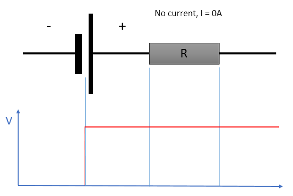
At rest, the output voltage reflects the state of charge of the battery.
If no current is flowing, the internal resistance has no effect on the output voltage; this is why it is important to measure cell voltages at rest if the objective is obtaining an idea of the state of charge. Otherwise, the effect of electrical resistance is skewing the voltage proportionally to the current according to the relation:
ΔV = R x I
Upon discharge, we can now observe the following effect, which does model the reality of a battery discharging at a steady rate:

Under discharge, the voltage at the terminals is lower than the true voltage of the cell because its internal resistance is introducing a loss equal to R x I in the direction of the current.
As a consequence, the voltage measured at the terminals of the battery no longer reflect its state of charge. This is why the state of charge of any battery can only be deduced from a stabilised voltage measurement taken at rest: it is called the stabilised open-circuit voltage (OCV). A similar situation arises when charging:

While charging, the voltage at the terminals is higher than the true charging voltage of the cell because its internal resistance is introducing a loss equal to R x I in the direction of the current.
Now, the internal resistance of the battery is making the charging voltage at the terminals look higher than it actually is in terms of actual state of charge of the battery. Here is a real-world illustration of this behaviour:
We were in the process of building a brand new lithium iron phosphate battery bank on a sailing catamaran, charging 400Ah of cells for the first time with both engines running. The charging current had been a solid 180A for almost an hour. The cell voltages, which had initially jumped up around 3.40V, were gradually rising. When they reached 3.60V, we shut one engine down in order not to exceed this value, reducing the current by half, down to 90A.
The cell voltages instantly dropped down to 3.45V.
We therefore lost 0.15V in cell voltage by reducing the current by 90A. We can use these figures to calculate the internal resistance of the cells using the relation presented earlier, ΔV = R x I:
In this case, we have ΔV = 0.15V and I = 90A. As a result, we can write R = ΔV / I = 0.15 / 90 = 1.66mΩ
1.66 milliohms is a very small resistance figure typical of lithium battery cells, but it is nevertheless enough to significantly skew the voltage reading at high amperage. At a current of 10A, its contribution becomes only ΔV = R x I = 0.00166 x 10 = 0.0166V = 16.6mV, but still enough to be measured. We will refer to this again when discussing alternator voltage for charging, low voltage cut-off limits and cell balancing boards amongst other topics.
In a bank, all cells don’t share the exact same internal resistance, so their voltage doesn’t automatically read the same when there is current flowing, even when their state of charge is identical. It becomes increasingly true as cells age.
Before moving on, let’s point out that the battery model we used above featuring the cell internal resistance is correct as long as the current is steady and the voltage at the terminals has had a few seconds to stabilise. A more complex electrical model would need to be used if the transitions when the current varies were of interest, because of capacitance effects.
Battery Currents
Current measurements related to batteries in general are expressed in relation with their capacity rather than in absolute terms: a 100Ah battery operated at 100A is said to be charging or discharging at 1C: one time its capacity rating. A 10A current would only amount to 0.1C; a full charge at a rate of C/5 would represent a 5-hour (approximately) charge, etc.
Charge and Discharge Ratings
Prismatic LiFePO4 battery cells were once rated for charge at up to 1-2C and discharge to 3C, and this seemed to imply they could theoretically be charged in 30 minutes and discharged in 20 minutes. We since realised that most lithium-based chemistries didn’t last long when subjected to this kind of treatment. Excessive charging currents in particular are damaging and even more so at lower temperatures.
The maximum recommended routine charge and discharge rate became about 0.3C for long-term, sustained operation. Some of the newer-generation aluminium-cased LiFePO4 cells are rated for 0.5C and this results in minimum long-term sustainable charging times of about 2.5 hours when absorption is factored in. This can lead to having to limit charging currents and can discourage the use of ridiculously oversized alternators or chargers.
Beware of Short-Circuits
The short-circuit current capacity of LiFePO4 cells can easily exceed 20-30C, which is far more than needed to cause catastrophic heat damage. The greatest of precautions must be taken when working around cell connections as dropping a non-insulated tool onto any battery bank can result in molten metal flying around, a fire, disastrous burns or any combination of the three.
The practical difference between working near the common deep-cycle lead-acid batteries on board and working around lithium cells is that there are a lot more exposed connections in much closer proximity and even small tools or metallic objects can be long enough to cause a short-circuit. Furthermore, in the event of short-circuit, even relatively small lithium cells are capable of delivering extremely intense and sustained currents.
Incidentally, manufacturer tests have repeatedly shown that a healthy LiFePO4 cell can be bluntly short-circuited to complete destruction without reaching ignition temperature: this is due to the fact that its internal resistance is very low. The same may not hold for a previously damaged cell with an elevated internal resistance and the outcome could then be extremely different.

A short-circuit test on a fully charged Sinopoly cell. The current is exceeding 1800A as the cell is venting profusely.
This image was extracted from a video released by Sinopoly Battery Ltd, China, where other common battery failure modes were investigated, such as when a crew shoots into the battery with an automatic pistol.
Typical Cell Operating Limits
Manufacturers ratings for LiFePO4 battery cells have become more conservative in recent years as more experience was gained with the practical operation of these cells. Nowadays, the typical operating specifications for LiFePO4 prismatic cells [1] look as follow:
| Charging | Maximum charge voltage | 3.65V |
| Recommended charge current | 0.3C | |
| Maximum charge current | 1-2C | |
| Cut-off current | 0.033C | |
| Charging temperature range | 0°C – 45°C | |
| Discharging | Minimum discharge voltage | 2.5V |
| Recommended discharge current | 0.3C | |
| Maximum discharge current | 2-3C | |
| Discharge temperature range | -20°C – 55°C | |
| State of Charge | Recommended operating window | 10-90% SOC |
Back in 2007, Thundersky, a manufacturing company later absorbed by Sinopoly Battery Ltd, was advertising its prismatic cells for charge up to 4.25V using a current of 3C and their maximum rated discharge current was 10C. Those who followed these guidelines quickly came to a great deal of grief, first and foremost with charging, destroying cells left, right and centre while charging up to the 4.25V “target” at low current.
Today’s charging specifications may still appear as being on the high side, but they must be understood in the context of a constant current/constant voltage (CC/CV) charge regime with charge termination and charging to maximum capacity as the aim. The recommended upper SOC limit is 90% however, not 100%, and charging to 100% SOC in this context means absorbing the cells at 3.65V until the residual current is C/30. Anything short of this will not – by definition – achieve 100% SOC.
All maximum ratings must be understood as absolute limits, not standard operating values, which is why the simplistic reasoning suggesting that 4 cells in series can be charged at 4 x 3.65V = 14.6V couldn’t be more wrong. Just as wrong as the suggestion that any old lead-acid charging system is fine for operation with lithium cells “because the voltage range is compatible”. The voltage range can be quite close, but the charging process required is very different because it needs to provide for charge termination.
The specifics of charging lithium cells on board will be the subject of a separate article due to the extent of the subject, but the essential charging characteristics of LiFePO4 cells are discussed further below.
Battery Capacity
Peukert’s Law and Lithium Batteries
The capacity of a battery is not a constant figure: it depends on the charge and discharge current. The phenomenon was documented whilst working with lead-acid batteries as Peukert’s Law in 1897. In simple terms, Peukert’s Law states that the available capacity shrinks as current increases.
The answer to the question of whether Peukert’s relation can really be applied to lithium chemistries is essentially negative [2], but the capacity of Li-ion batteries does also vary with discharge current and Peukert’s Law is all we have at present. Peukert’s Law was only ever formulated to be valid at constant temperature and we do know that Peukert’s effect in LiFePO4 batteries becomes increasingly noticeable as temperature drops below 15°C.
Peukert’s relation is characterised by a supposedly constant exponent k and, in the case of LiFePO4 batteries in house bank applications, experimental data at modest temperatures has suggested a value of k=1.04. An exponent of k=1.00 would indicate no dependency between storage capacity and current, i.e. an ideal battery, and lead-acid batteries often score around k=1.25, with the figure getting worse as they age.
Configuring Battery Monitors
This value of k=1.04 can make for a useful starting point when configuring battery monitors, but temperature variations (which are never accounted for) can easily throw the calculation out, especially when large swings from winter to summer are involved. In the tropics, with batteries at 25°C or over, a value of k=1.02 for the exponent may be more appropriate.
Trying to configure battery monitors designed for lead-acid batteries – where they already perform suspiciously at the best of times – to operate with lithium cells is fraught with uncertainty: the supposedly constant exponent k has been shown to be anything but constant with lithium-ion chemistry [3]. Provided the temperature doesn’t change significantly and the currents in operation are reasonably consistent, a set of parameters can be derived to obtain seemingly sensible readings.
Rated Capacity and Actual Usage
Lithium cells are usually capacity-rated at much higher currents than lead-acid batteries and the battery is deemed discharged when it can no longer supply the discharge current. Capacity rating for discharge at 0.5C (2-hour discharge) or 0.3C are common for prismatic lithium cells, while lead-acid cells are normally rated at C/20 (20-hour discharge). The practical consequence of this is that lithium batteries commonly appear to exceed their capacity ratings at the average currents normally run on board a yacht.
Peukert’s Law can be formulated as: C2 = C1 x [ C1 / (I2 x T1) ] (k-1), where:
C1 is the battery capacity when discharged in T1 hours at a current I1, and
C2 is the calculated capacity when discharged at a current I2. k is the Peukert exponent discussed earlier.
What can we expect from a 100Ah lithium battery rated at 0.5C = 50A when used as a house bank and discharged at C/20 = 5A instead?
We have C1 = 100Ah, I1 = 50A, T1 = 2 hours, I2 = 5A and we will use k = 1.04:
C2 = 100 x [ 100 / (5 x 2) ] (1.04 – 1) = 100 x 10 0.04 = 109.6Ah
The same 10% gain stands for a 200Ah battery discharged at 10A, etc.
| Rated lithium battery capacity at 0.5C | Discharge current at C/20 | Effectively available capacity |
| 100Ah | 5A | 109.6Ah |
| 200Ah | 10A | 219.2Ah |
| 300Ah | 15A | 328.8Ah |
| 400Ah | 20A | 438.4Ah |
These differences can become quite significant in larger banks, as a 400Ah battery discharged at 10A only would now exhibit a theoretical capacity of 476.6Ah. Such calculations are fraught with uncertainty however due to the temperature dependency for the value of k, but matching results have been demonstrated experimentally. At very low temperatures, some of the battery capacity simply becomes inaccessible altogether.
Low Temperature Effects
Capacity Reduction
Capacity is also quite sensitive to temperature effects. Lithium cells offer more capacity and higher performance at higher temperatures, including at excessive temperatures causing accelerated ageing. At freezing temperatures, the available capacity upon discharge shrinks quite significantly [4], but is recovered once the cell warms up again.

Available capacity as a function of temperature for a low voltage discharge cut-off threshold of 2.5V/cell (Plot courtesy of Tsinghua University)
This phenomenon highlights the fact that lithium ions become more and more difficult to extract from the graphite matrix of the anode as temperature drops and only relatively superficial charge carriers are available at low temperatures; the balance of the capacity effectively becomes “locked-in” out of reach. This loss of available capacity also translates into a lower discharge voltage, with the low voltage cut off point being reached earlier.
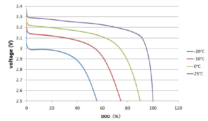
Constant current voltage discharge curves at different temperatures. The low voltage cut-off threshold leaves significant capacity locked into the battery at freezing temperatures (Plot courtesy of Tsinghua University)
Accepting a lower low voltage cut-off threshold would be a way of regaining access to some of this locked-in capacity in sub-freezing conditions, but the matter is only of real interest for automotive applications.
| Cut-off voltage = 2.5V | Cut-off voltage = 2.0V | |
| T = 25°C | C = 100% | |
| T = 15°C | C = 98% | |
| T = 0°C | C = 90% | |
| T = -10°C | C = 74.5% | C = 87% |
| T = -20°C | C = 56% | C = 72% |
For all practical purposes on marine vessels, battery temperatures below freezing should be uncommon unless the water also freezes around the hull. Capacity reduction is then limited to about 10% only in the worst case, which should be negligible. While discharge at low temperature yields both reduced power and capacity, it is harmless to the cell. The same cannot be said of low temperature charging.
Cold Temperature Charging
Cold temperatures are known to be detrimental to the cells if they are exposed to charging. Cycling performance tests at varying temperatures showed the apparent existence of a threshold below which capacity fade with cycling suddenly accelerated. This threshold appeared to be above the temperature of 0°C often suggested as limit for recharging, but the data available was limited and the exact details of cell manufacture are likely to influence this value.
The intercalation of lithium ions into the graphite matrix of the anode becomes more difficult as well at low temperatures and lithium ions ejected out of the cathode and unable to soak into the anode instead plate its surface and edges; this lithium is then irreversibly lost. This suggests that fast charging in particular becomes increasingly harmful to the cells as temperature drops.
Impact of State of Charge and Temperature on Capacity and Cell Life
The cell voltage naturally increases with their state of charge and the higher voltage makes the electrodes chemically more reactive and this appears to encourage undesirable side reactions with the electrolyte that harm the cell health. The practical consequence of this is that keeping lithium cells at a high state of charge for long periods reduces their working life by causing capacity loss and an increase in internal resistance. Higher temperatures are well-known to reduce cell life.
The combined effects of state of charge and temperature on cell health during a storage period of 9 to 10 months were studied in detail by Keil et al. [8] and illustrated below.

LiFePO4 cell capacity and internal resistance changes over a 9-10 months storage period as a function of state of charge and temperature (plots from Keil et al. [8]).
The first plot clearly illustrates that cell capacity is best preserved by storing the cells at the lowest state of charge and temperature, with virtually no degradation occurring at 0% SoC and 25ºC. If we compare the plot with the graph of the cell open-circuit voltage presented in the next section below, we can see that capacity fade then increases in direct relation with the cell open-circuit voltage and this translates into a step change above 70% SoC and a flat between 40% and 70% SoC. This indicates that LiFePO4 battery banks should be stored at a very low voltage, like 3.0V/cell and in cool conditions, with temperatures up to 25ºC being acceptable, but lower being even better.
The second plot depicts the effect of SoC and temperature on the DC internal resistance of the cells and shows that this is unrelated to the state of charge and dependent on temperature only. Not only banks stored in warm conditions lose capacity at an accelerated rate, but they also develop increased voltage sag under load and this reduces their ability to supply high power levels.
Voltage and State of Charge Characteristics
A LiFePO4 cell has a rated nominal voltage of 3.2V. In practice, 3.2V is only reached when heavily discharged (or under significant load) and the normal operating voltage is about 3.3V. This implies that a 12V nominal lead-acid battery made up from six cells in series for a total of about 12.7V in operation can be substituted with four LiFePO4 cells instead, for a resulting voltage of about 13.2V.
On-board power from a lithium bank shows an improved and much more constant system voltage; most of the equipment runs noticeably better, from pumps to SSB transceivers. Lights don’t dip either when a load is turned on, because its low internal resistance translates into much less voltage sag.
The state of charge (SOC) of a lead-acid battery can normally be deduced from its voltage, but only as long as the battery has been at rest long enough for the reading to stabilise. Lead-acid batteries have significant internal resistance, especially when no longer in their prime and drawing current from them immediately skews the reading to the downside.
Lithium batteries are similar, other than for their much lower internal resistance and a more complex relation between state of charge and voltage, which exhibits a prolonged flat when the cells are in the 40% to 65% SOC range. Outside of this region, voltage readings do provide very useful indications of the state of charge.

Single LiFePO4 cell stabilised open circuit voltage as a function of the state of charge (Data courtesy of Tsinghua University)
The cell voltage differs depending whether the cell was being charged or discharged before the voltage was allowed to stabilise. In nearly all instances on board yachts, small loads quickly bring the voltage back in line with the discharge curve.
If this higher resting voltage following charging appears to dissipate very quickly, it is a tell-tale sign that the cells have been abused and suffered electrochemical damage.
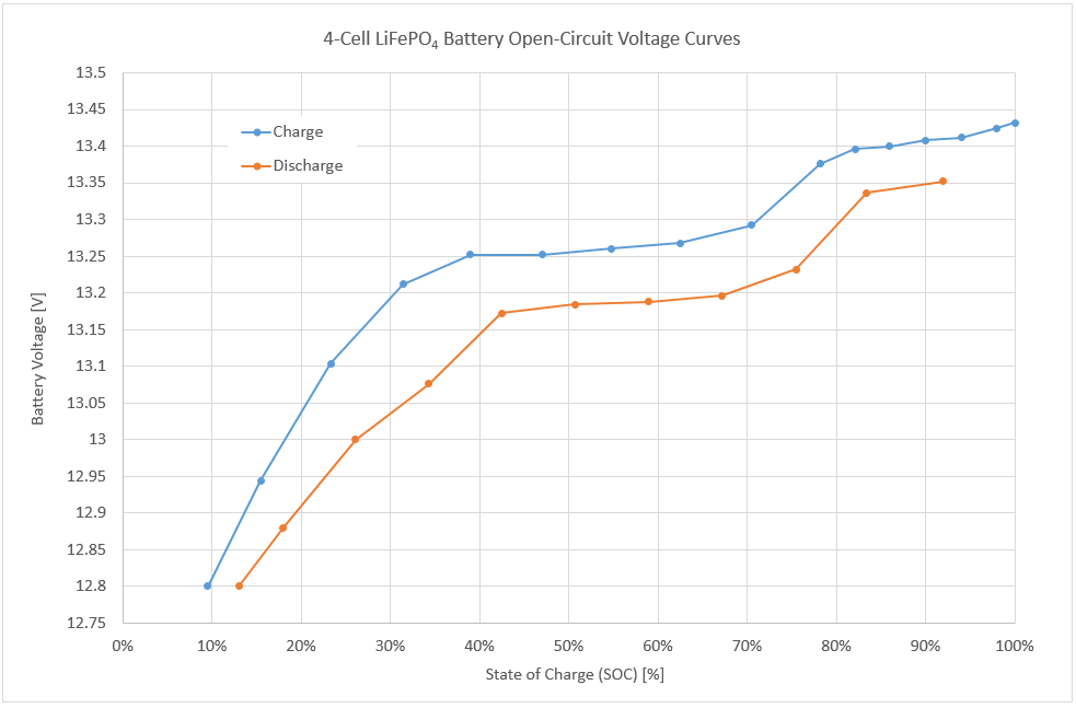
LiFePO4 4-cell battery stabilised open circuit voltage as a function of the state of charge (Derived from data courtesy of Tsinghua University)
At rest, or for low charge and discharge currents, the above plots are extremely useful for estimating the state of charge, even just by glancing at the voltmeter:
| Voltage reading | Assessment | Capacity |
| 13.3V or more | Near full | Over 80% |
| Above 13.2V | Plenty of reserve | At least 70% |
| Below 13.15V | Getting on the low side | Less than 40% |
| Below 13.0V | Definitely getting low | Less than 25% |
The owners of installations cycling moderately who can refrain from making an automatic beeline to the nearest marine electrical retail store can be pleasantly surprised to discover that the addition of a random number generator battery monitor to the system can be completely superfluous with lithium, as long as a simple voltmeter and a little knowledge are available.
Current and Power Efficiency
Lithium batteries in general are near 100% current efficient: this means that charging 1Ah yields a typical discharge of 0.997Ah at a similar current. This is hugely higher than what lead-acid chemistry can achieve and often results in gains of 30-50% in charging efficiency when a lead-acid house bank is replaced by LiFePO4 cells on a yacht.
The net effect with solar arrays is as if the size of the array had suddenly become significantly larger and a change to a LiFePO4 bank can be a more sensible answer to energy issues than adding more panels or running an engine.
Power efficiency, on the other hand, sits around 95%, but varies with current: expend 100Wh charging and you will retrieve about 95Wh on discharge. The difference stems from the fact that the charging voltage needs to be a little higher than what is available afterwards during discharge.
In marine use, current efficiency is what matters, because finding a little more voltage is never an issue.
Charging Characteristics
With regard to charging, lithium cells are both far simpler to charge and totally different than lead-acid cells. As a consequence, they should also be managed differently. Another important aspect is that recharging a fresh, new cell can be very different and much easier than recharging a cell which has just seen a large number of partial charge and discharge cycles, due to memory effects which are discussed further below.
The most commonly documented charging regime for lithium cells is constant current, constant voltage (CC-CV). It is also one that is essentially never achieved with marine installations: on-board systems deliver variable current, limited voltage mixed with partial charge/discharge cycles.
As a result, the only parameters that actually matter are the maximum voltage the battery is allowed to reach during charging and the way the charge is terminated, because those determine the outcome of the charging process.
What is Charging Voltage?
The charging voltage is basically the voltage at the battery terminals during charging. The battery user essentially has no control over this voltage for most of the charging process: the battery absorbs all the current provided and the voltage rises at its own pace, as the state-of-charge increases.
The voltage can only be controlled – by reducing the charging current – once it would start to exceed a limit.
I remember once reading a senseless post about an alternator. The author was complaining that the regulator was “useless” because “it limited the voltage instead of charging at the desired setpoint”.
What this person didn’t understand is that the voltage reaches a value that depends on the state of charge of the battery and, with the alternator at full output already, there is nothing more the regulator can do until the voltage naturally rises enough to warrant limiting it.
The parameter the user has control over is the end-of-charge voltage. The end-of-charge voltage is simply the voltage limit used by the charging system before the charge is terminated. Because of the higher internal resistance of lead-acid batteries, the charging voltages rises both earlier and a lot more rapidly than what is observed with lithium cells.
Lithium cells commonly charge at 3.4V or less for very long periods of time while soaking up full current and, when the voltage finally begins to increase, the battery is already significantly charged.
The Relation Between End-of-Charge Voltage and State of Charge
The relation between the end of charge voltage and the state of charge eventually achieved by a LFP cell can be explored by charging battery cells using a range of maximum voltage limits until the current has reduced down to a very small value each time before discharging them again to assess capacity.
Such an experiment was conducted by Powerstream [5] in 2014 with four different brands of LiFePO4 cells of the same size, which were charged until the current had reduced down to about 0.013C. This is quite a low charge cut-off current and it must have resulted in extended absorption times.
I used their published experimental data to plot a more interesting graph showing the state of charge reached against the absorption voltage limit.

The graph above illustrates that while 3.3V is insufficient to recharge a cell, 3.4V is enough to obtain near 100% capacity already and limiting voltage cannot realistically prevent overcharging without also compromising charging.It also highlights that using high absorption voltages essentially fails to achieve anything as far as capacity is concerned, but charging times would certainly be reduced if also shown.
LFP cells simply don’t really charge at voltages up to 3.3V and then fully charge already at 3.4V and upwards. The transition is so abrupt that claiming to control the charging process by adjusting the voltage is purely and simply bound to fail.
Charging at reduced voltages, down to 3.4V/cell, only increases the absorption time and therefore the overall charging time, but achieves strictly nothing in terms of preventing the battery from getting fully charged and then overcharged. It only takes longer for this to happen. Furthermore, low-voltage charging opens the door to severe longer term performance issues which arise from memory effects in the cells.
Memory Effects
Memory effects in LiFePO4 cells were discovered and studied by Sasaki et al. [6] and the results published in Nature Materials in 2013. The authors illustrated that, under specific circumstances, the prior cycling history of a cell alters the voltage curve during charging by causing the voltage to increase faster and earlier than expected.
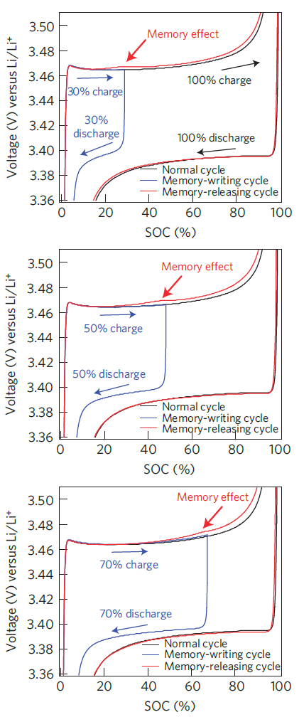
Memory effect in LFP cell following different incomplete charge and discharge cycles. Note that the voltage is referred to the potential of a lithium electrode (plots from Sasaki et al. [6]).
For a memory effect to appear, an incomplete charge cycle followed by a rest period and a discharge must have taken place earlier (memory-writing cycle). A partial charge followed by an immediate discharge is not sufficient to record a memory of the incomplete cycle [7]; this is important because the practical consequence is that a charge-and-hold strategy is particularly harmful when full charge was not achieved. It is not uncommon for DIY lithium battery systems to implement deficient charging strategies which in fact result in this scenario taking place and it is detrimental to the long-term performance of the battery bank.
When a memory-writing cycle has been completed, an abnormal increase in voltage can be observed afterwards as the charging process approaches the point where charging had stopped earlier; this creates a bump in the charging curve. Partial charging of all common types of lithium cells (with the notable exception of lithium titanate oxide Li4Ti5O12) leaves the cell with divided lithium-rich and lithium-poor phases which persist during and after discharge. In order to erase the cell memory of the previous interrupted cycle(s), a full charge must be performed (memory-releasing cycle) and this requires overcoming the bump caused by past partial cycles.
The memory effect was found to strengthen with the number of incomplete charge cycles performed before the erase cycle. It was also strengthened when a partial charge was followed by a shallow discharge, rather than a deep discharge.
These latter aspects have proved to be of key significance when considering the longer term performance of LiFePO4 batteries in house bank applications, because incomplete charge cycles are common when relying on renewable energy sources and shallow discharge cycles are also frequently experienced. These have the potential to render battery banks near unusable after as little as 2-3 years in regular service in the absence of memory-releasing cycles. Ineffective memory-releasing cycles are very common in DIY installations where the charging process is not properly controlled and/or configured incorrectly by fear of overcharging or due to widespread mythologies.
An absence of memory-release cycles caused by ineffective charging allows the voltage bump caused by the memory effect to grow over time. If the absorption voltage and/or the absorption time are insufficient to overcome it, the charging process gradually terminates earlier and earlier. This has a compounding effect as memory-writing begins to occur at lower and lower values of SOC over time and the available capacity of the battery can disappear almost completely without any loss of lithium or chemical degradation as such. Recovering battery banks in this state can be challenging and require many memory-release charging cycles using high absorption voltages, followed by deep discharge. For these reasons, LiFePO4 batteries should be charged properly whenever the opportunity arises, so the effects of unavoidable previous partial cycles can be wiped out while it is still relatively easy to do so. This calls for a robust absorption voltage and a charging strategy providing adequate charge absorption. Anything else falling short of this will eventually result in significant performance and capacity issues.
While we showed earlier that voltages as low as 3.4V/cell were able to fully charge and even overcharge a LFP cell, this must now also be considered in the context of memory effects altering the charging curve of the cells. My experience so far has been that any termination voltage below at least 3.5V/cell should be considered as inadequate if the installation experiences incomplete charge cycles. Any charging system that is unable to provide an adequate absorption down to at least C/20 or less when required should also be considered as unfit for purpose, because it will fail to deliver charge cycles capable of erasing the cell memory.
Overcharging
Overcharging means applying a charging voltage to an already fully charged battery. As we just highlighted the fact that – given enough time – lithium batteries always fully charge at 3.4V/cell or above, any voltage from 3.4V up can most definitely overcharge and damage a lithium battery.
How quickly this happens certainly depends on how high this voltage is, but – unlike what is observed with lead-acid chemistry – there is no such thing as a safe charging voltage that can be maintained continuously with lithium cells. All charge cycles must end when or before the battery becomes full.
A lead-acid battery benefits from what is known as a shuttle reaction, which does (within reason) allow excess energy to be absorbed and dissipated. This mechanism is not present in lithium batteries and it makes them very intolerant to overcharging.
A lithium battery that is being held at an elevated voltage with zero current flowing in has been overcharged and is getting damaged. This situation commonly happens with many marine charge controllers, including and especially some supposedly designated for lithium banks.
The “lithium” versions of the Genasun GV-5 and GV-10 MPPT solar charge controllers are prime example of this as they maintain 14.2V on the battery indefinitely (based on units inspected in 2015)
Charge Termination
Since absorption voltage can’t practically be used to limit charging, it becomes a matter of determining when to stop. Charge termination ideally needs to occur before the battery is completely full, because most of the stress on the battery happens when it runs out of lithium to transfer, or when it can’t transfer lithium ions fast enough, such as when the charge rate is very high and the voltage is allowed to rise excessively.
The tell-tale sign of a fully charged (or overcharged) battery is that it is no longer able of absorbing any significant current, or even any current at all
Voltage-Based Termination
If charging at very low currents, such as 0.05C, where internal resistance doesn’t meaningfully skew the voltage reading, termination can be implemented based on a voltage threshold on the basis that the current is then known to be low. A small solar system charging a sizable bank can fall in this category. In this case, charging must stop when the target voltage is reached and not resume until the voltage has dropped to a level indicating that the battery can and needs to be recharged again.
At higher currents, this strategy would err on the safe side by leaving an undercharged battery, but it is unsatisfactory, because charge absorption is still essential with lithium cells in order to erase the memory from previous partial cycles and make a good use of the capacity installed.
Time-Based Termination
Schemes involving a timed absorption period perform an approximate charge termination only. If the battery requires bulk charging and the duration of the absorption period has been determined wisely, a good charge cycle may result. If the battery is already full when charging begins, it will invariably suffer throughout the undesirable absorption phase; using a lower absorption voltage limits the stress placed on the cells, but fails to properly address the issue, increases the overall charging time and opens the door to long-term capacity problems resulting from memory effects.
Nearly all so-called “smart” alternator controllers typically implement a time-based absorption strategy to provide a charge termination that is anything but smart… any charge termination is still a lot better than none however.
Absorption times with lithium iron phosphate batteries are typically in the 30-40 minutes range in most situations when charging with high-current sources, and much less if the battery is being charged at low current. If a time-based termination is going to be implemented, then the absorption time should be determined experimentally by monitoring the current taper. If the battery is suffering from memory effects due to previous repeated partial charge cycles, then the required absorption time can increase very significantly and a time-based termination will interrupt the charge before the cell memory has been cleared.
Optimal Charge Termination
In all instances where significant charging currents are present or where the battery has seen a large number of interrupted and partial charge cycles, correct termination can only be obtained by monitoring both current and voltage to make an informed decision.
The voltage must be up at the absorption setpoint while the current is down at the charge termination limit; this indicates that the ability of the battery to absorb further charge is near its end. The final state of charge achieved depends on the combination of maximum voltage and minimum current, but changing the termination current is the only reliable way of altering the state of charge obtained and the voltage must always be sufficient to ensure memory effects from previous partial cycles can be overcome.
Charging equipment intended for lead-acid batteries is hardly ever able to perform a proper charge termination, because overcharging lead-acid cells (with the exception of gel-cells) is acceptable to some extent, there are no real safety considerations arising and batteries are relatively inexpensive. The functionality required is not present and the addition of the word “lithium” in the product brochure typically does exactly nothing to remedy to this situation. While battery voltage is always available, battery current is either not measured or the information is not exploited by the equipment. For this reason, the only place for realistically determining charge termination in a lithium battery system is at the BMS and the BMS should supervise the charging process.
References:
[1] CALB CA180FI and Sinopoly LFP200AHA cell datasheets.
[2] D. Doerffel, S.A. Sharkh, A critical review of using the Peukert equation for determining the remaining capacity of lead–acid and lithium-ion batteries, Journal of Power Sources, 155 (2006) 395–400
[3] N. Omar, P. Van den Bossche, T. Coosemans and J. Van Mierlo, Peukert Revisited—Critical Appraisal and Need for Modification for Lithium-Ion Batteries, Energies 2013, 6, 5625-5641; doi:10.3390/en6115625
[4] L. Lu, LiFePO4 battery performance testing and analysis for BMS, Department of Automotive Engineering, Tsinghua University (2011)
[5] http://www.powerstream.com/lithium-phosphate-charge-voltage.htm
[6] T. Sasaki, Y. Ukyo and P. Novak, “Memory effect in a lithium-ion battery”, Nature Materials, Vol. 12, June 2013; doi:10.1038/nmat3623
[7] , , and Comprehensive Study of the Polarization Behavior of LiFePO4 Electrodes Based on a Many-Particle Model”, J. Electrochem. Soc. 2018 165(10): A2047-A2057; doi:10.1149/2.0181810jes
[8] P. Keil, S. F. Schuster, J. Wilhelm, J. Travi, A. Hauser, R. Karl and A. Jossen, “Calendar Aging of Lithium-Ion Batteries, I. Impact of the Graphite Anode on Capacity Fade”, Journal of The Electrochemical Society, 2016 163 (9) A1872-A1880
“Optimal Charge Termination
In all instances where significant charging currents are present, achieving proper termination requires monitoring both current and voltage to make an informed decision.”
This approach does not work well when the charging power available is variable: like with PV sources on a moving vessel with variable PV shading by sails and masts, which will produce output current dips that do not relate to battery SOC. Instead, I am using coulomb counting: measuring amp/hours in and out. When my bank reaches 80% SOC, I terminate charging. This requires occasional recalibration, I set 50% SOC as a floating voltage of 13.18 volts.
Patrick,
Charge termination based on residual current always works and it is the only correct way to terminate. An output current dip caused by external factors produces a corresponding voltage dip and the termination condition is not met. From a practical implementation point of view, charging is a slow and gradual process and it is common to impose that the termination condition V > V_target and I < I_residual needs to last from a few seconds to a few minutes. This further protects the algorithm from false positives.
Coulomb counting is notoriously unreliable, i.e. impossible to carry out accurately, and terminating charging “at 80%” is nonsensical. Lithium iron phosphate cells need to be recharged correctly (which means fully and without overcharging) at least from time to time when the opportunity arises in order to erase the memory effects caused by partial cycles. When this doesn’t happen, the available capacity shrinks over time and the system eventually becomes unusable.
The whole “incomplete, weak charging theory” originated from: 1/ a technical inability to correctly implement charge termination and, 2/ the operation of banks without cell balancing, which drift out of balance and start causing voltage issues near the top after some time. However, it is garbage and leads to bigger issues a little further down the track.
Eric
I am about to install a DIY 400AH Winston (8 cell 24V) system.
I have a victron 100/50 Solar Charge controller, and a 3000/24v 70Amp inverter charger. 30A DC to DC charger
First of all I read about low current 0.05C – 0.033% (for me looking at 20A or greater when installed 8S) which means my original idea for initial top balancing of using a 10Amp power supply is out, even on a single cell but in a paralleled bank totally out.
So for initial top balance
Instead, stop the charging process, let the cells rest for a few hours, and measure the terminal voltage. When the resting open-circuit cell voltage reaches 3.35 volts (measured with a very accurate meter), you are done. Stop there!
For normal operation
I can program the changers (also have a programable BMS for cell / secondary protection)
-Solar 1300W PV array but that is max in theory, stop on voltage with no absorption? In theory sometimes it could be putting out more 20A, like twice that would I be better treating it is a larger current and have some absorption time (lower voltage)
30A DC to DC charger voltage with absorption time (at a lower voltage?)
Victron 70A inverter/charger absorption time (at a lower voltage?)
Your recommendations would be appreciated. I want to protect my investment in the battery bank.
Hello Francis,
0.033C for a 400Ah bank is 13.2A termination current, so 10A is close enough and you should be able to charge new cells up to 3.65V and stop. There is no need to make things more complicated than they are. It is just a one-off charge of a battery.
No absorption is out of the question with LiFePO4 cells. The absorption time needed varies considerably with charge current and cell health. If the bank has seen a lot of incomplete charge cycles, memory effects become very significant and lead to very long absorption times. If you are not charging up to a correct termination point, a lot of capacity becomes unreachable after a few years… or less.
I am currently carrying out some tests on clearing the memory effect on a bank which has done hundreds of partial cycles and I will release the data in an article when I am done.
Lead-acid chargers by themselves are basically incapable of charging a LiFePO4 battery properly in all circumstances where loads are also present. You should be getting the charge termination signal from the BMS and make the chargers comply with it. Fudging things sort of works for some installations, at least for a while, but it eventually falls apart when the bank can’t be recharged to full frequently enough. It is not so much about what you buy, but rather about how you design and build the system.
Regards,
Eric
My LFP bank was designed to sustain the essential electronics in my sailboat for 96 hours without a charging source. My only charging source underway is solar. So my discharge rate is C/96 (to 10% SOC) and my charge rate (worst case estimate) is C/48 (to 90% SOC).
Under these conditions, how does one possibly detect C/20 (0.05C) for charge termination – when that current is more than twice the charge current available? That is why I count amp/hours in and out instead. To prevent memory effect, I charge the bank to 100% SOC on a shore power charger using current taper detection (C/20) approximately every 25 cycles.
I have over 500 cycles accumulated over 3 years and I cannot detect any memory effect in my bank (400A/H 4S 4P GBS cells). The bank terminal voltage always rests (24 hours resting OCV) to 13.43 volts for an indicated 100% SOC charge, and the 24 resting OCV tracks all along the discharge curve within a few percent.
The published advice completely disregards the practical needs of sub-fractional users such as myself. Not everyone has an engine-driven alternator. I have no alternator at all. I have a sailboat — not an “wind-assisted motor boat” (auxiliary sailing vessel).
It is not because a boat has an engine and alternator that the energy comes from there. There is nothing uncommon to using solar for most of the charging, at low C-rates, and even extremely low C-rates in adverse conditions. Manufacturers specify charge termination at 3.65V when the current is down to C/30 = 0.033C and the charge rate was C/3 typically. As long as the battery is absorbing and the voltage doesn’t skyrocket, it is charging. There is nothing to get excited about. If you charge and discharge at very low currents, you will be able to access more capacity because there is more time available for diffusion processes. When you terminate charging at voltages lower than 3.65V, you also need to charge to a lower residual current to reach the same SOC anyway.
As long as you have the opportunity to recharge properly from time to time, there is no reason why memory effects shouldn’t clear easily and they do. Things become more challenging when you DON’T have the opportunity to recharge to full for very long periods and keep cycling.
You write “the bank terminal voltage always rests (24 hours resting OCV) to 13.43 volts” and so by definition there is nothing else to do about “memory effects”, because that is a full charge and possibly even an overcharge.
Coulomb counting is NOT RELIABLE because you can’t have an instrument that is going to cope perfectly with a dynamic range of current extending from milliamps to hundreds of amps. As soon as you start metering, you also start accumulating measurement errors and very quickly you have NO IDEA about what the true state of charge actually is. So common sense suggests NOT to use this information to make critical decisions, unless you also have a measure of the quality of the SOC based on how hold it is and other parameters and you can make intelligent decisions integrating cell voltage, current, estimated SOC and SOC quality. There are no “special reasons and circumstances” for ignoring this and doing it anyway, because 1/ you haven’t addressed the reason why it should not be done in the first place and 2/ experience shows that there is no need for ever doing it when you are able to periodically recharge properly.
I’m a little late to the party here, but I have to ask: how often should a full charge be accomplished to wipe memory effects before they become permanent? Once a month? 6 months? a week? I’ve got 3 55A Midnite Classic 250s charging my 50kwh LFP bank w/ a Radian GS8048 inverter. I can adjust the bulk and adsorption voltages & time, and turn off the float.
Nothing I have allows me monitor current and get that information into the Midnites or Radian in a useful way.
The only way I can see accomplish a periodic full charge is to set the equalize function to 3.6v/cell and the time to a value I establish w/ a current monitor to when the charge current gets to 0 or near 0 and then have it repeat once a week/month/etc.
If you have any ideas I’d love to hear them.
Thanks
David,
Memory effects don’t become permanent, they just become more difficult to overcome. Your question is difficult to answer because there is not much data available and it depends too much on the operating regime of the bank. Performing a full recharge once or twice a year would appear to be quite enough in most cases.
If you can’t monitor current and use this information, you can’t achieve a correct charge termination. The absorption time varies a lot with the condition (and age) of the cells, so trying to deterine a fixed absorption time is a flawed strategy. You must use voltage and current.
Trying to charge LFP banks with lead-acid chargers doesn’t work properly. The BMS must measure the current and be able to control the charge termination.
Best regards,
Eric
How do you develop relation between State of Charge and Battery open circuit voltage? Is there any direct formula for that? Any rule of thumb (if it exist) ?? I need to draw similar graph with 2 cell LiFePO4. Can anyone please help me. Thank you
Bishal,
You need to measure it, it is the only way and it should be done for a single cell. It takes a long time because you need to charge and discharge in incremental steps and wait for the open circuit voltage to stabilise afterwards each time. The relation appears to also change as the cells age, more for some cells than others.
Best regards,
Eric
Thank you Eric for your reply and for the article.
A very interesting report and I thank your for making it available.
My interest in Memory Effects is to understand how to properly manage LiFePO4 cells in stationary off-grid home power system, specifically I am concerned with partial (incomplete) charge and discharge cycles during winter months where Solar inputs fall (well) short of battery capacity. From your article I suspect a periodic deliberate manual complete discharge followed by utility or back-up generator recharging to fully-charged (as you define it) would provide a means to remove the memory effects of the battery bank and extend battery life/capacity over the long term. It appears to me this manual deep discharge and recharge “reset-cycling” (my own term) would be only be required semi-annually to ensure resetting the battery bank and prolong the health and capacity of the battery bank on a whole. Your commentary would be appreciated.
Robert Little
Robert,
Thank you for writing. Please note that the best way of not having to deal with memory effects is not to write memory cycles into the cells in the first place. As explained in the article, writing a memory cycle requires very specific conditions to be met: 1/ an incomplete charge cycle followed by 2/ a rest period without discharge. Off-grid systems tend to be powering loads more or less all the time, so avoiding a rest period following a partial charge is normally easy to achieve simply by configuring the charging process correctly.
The people who ran into serious issues with memory effects commonly used misconfigured charging systems with weak absorption voltages and excessive “float” voltages, thus systematically charging poorly and then preventing the battery from discharging for some time after that.
Deep discharge doesn’t really help with erasing cell memory. The memory survives deep discharge, it is the recharging phase that can erase it and the more ingrained the cell memory has become, the harder it is to erase it successfully, because the cell voltage rises abnormally early.
Kind regards,
Eric
With regards to the conditions to avoid:
1/ an incomplete charge cycle followed by
2/ a rest period without discharge
Is there an amount of, or rate of, or duration of discharge which is needed to avoid the memory write?
Eg, a BMS, or even a columb counter/volt meter will be placing a very minimal discharge on the cells. Is this enough to avoid the memory write event?
Rowan,
The goal of the discharge is to remove the particular distribution of the charge carriers left at the end of a partial charge cycle that leads to the memory effect. If you discharge too slowly and this distribution remains in place for too long, I would expect it to produce the undesired effect.
We know that this happens from practical experience: having a BMS or battery monitor has never stopped memory effect from occurring on an incorrectly managed battery bank.
Kind regards,
Eric