

Last Updated on 17 April 2022 by Eric Bretscher
This article is part of a series dealing with building best-in-class lithium battery systems from bare cells, primarily for marine use, but a lot of this material finds relevance for low-voltage off-grid systems as well.
Lithium iron phosphate (LiFePO4) battery banks are quite different from lead-acid batteries and this is most apparent when it comes to charging them. Lithium battery banks charge much more easily and overcharge just as easily. They degrade gradually when kept full for extended periods and can develop memory issues when cycled inadequately.
On the other hand, lead-acid batteries resist charging, are tolerant to – and even require – a degree of overcharging and degrade rapidly when not fully charged regularly. This has given rise to a range of technology to meet these needs: it delivers aggressive charging, always errs on the side of overcharging and tries to keep batteries full. Trying to use this lead-acid charging technology to charge lithium cells certainly charges the battery, but it also damages it, so in other words it doesn’t and can’t actually work properly. No amount of searching for the Holy Grail of Settings can offset inadequate charging system design or the use of inadequate equipment.
Disclaimer
A good understanding of DC electrical systems is needed to build and commission a lithium battery installation. This article is aimed at guiding the process, but it is not a simple blind recipe for anyone to follow.
The information provided here is hopefully thorough and extensive. It reflects the knowledge I have accumulated building some of these systems. There is no guarantee that it will not change or grow over time. It is certainly not sufficient or intended to turn a novice into an electrical engineer either. You are welcome to use it to build a system, but at your own risk and responsibility.
Lithium Battery Charging
At a glance, a lithium battery charges just like as a lead-acid one: its voltage rises as it absorbs current until reaching a limit that must be respected. This means that it follows the well-known bulk and absorption pattern of lead-acid batteries. Because lithium batteries accept charge much more readily, they reach a higher state of charge before absorption begins, no forced charging, “boost” and other gimmicks are required or even desirable and the absorption phase is comparatively short. Its duration depends on the absorption voltage, the charge rate, cycling history as well as the age and condition of the cells. At low charge rates, the absorption time can amount to very little or nothing and when charging at high currents, such as when using powerful alternators or chargers, absorption is very significant. It also becomes more significant as the cells age and their internal resistance increases. The consequence of this is that it is impossible to pin down any duration as to how long the absorption stage should last. There is no correct setting.
A typical charging cycle for a lithium battery on a marine vessel can be summed up as follow: the battery is charged with whatever current can be produced with an upper limit on the battery voltage. The exact absorption voltage limit isn’t important, because of the inherent trade-off that exists between absorption time and absorption voltage. As previously illustrated, given sufficient time, any voltage from 3.40V/cell up will eventually fully charge and then overcharge a lithium iron phosphate battery. Lower voltages will fail to charge it extremely quickly and voltage cannot be used as a mean to control the outcome of charging as a result and absorption voltage alone has no bearing whatsoever on the final state of charge reached. Absorption voltages above about 3.55V/cell quickly exacerbate small differences in cell balance and become impractical to operate at. In my experience, 3.50V/cell has been a very good conservative charging voltage for LiFePO4 battery cells; it is just high enough to perform some automatic cell balance corrections when needed and also sufficient to properly recharge cells that haven’t seen a full charge in a long time, or cells no longer in their prime. Charging must stop when the absorption current falls below the termination current threshold, because this means that the cells ability to absorb current has reduced down to the point where the cells must be considered to be full. Any further charging constitutes overcharging and leads to a point where the cell completely runs out of free lithium and no current can flow any more. Therefore the battery current is a critical piece of information and it must be known and used to control charging.
While lithium battery cells are capable of charging extremely fast and absorb current at rates of 1C and more during the bulk stage, this is not desirable and can progressively cause irreversible damage as developed here. Newer generations of LiFePO4 cells are rated for regular charging at up to 0.5C and older ones usually 0.3C, so, in other words, even for modern cells a full charge can’t be achieved sustainably in less than about 2.5 hours when absorption is taken into account. This only becomes a concern when the capacity of chargers or alternators is very significant in relation with the size of the bank, but it also means that ridiculously large alternators are not actually as usable as some hope on small vessels. This can prompt using current-limiting chargers or regulators in some cases. Current acceptance capability also reduces with temperature, usually once outside the window of 5°C to 55°C (40°F to 130°F).
Charge Termination Condition
The charge termination parameters are nominated by the cell manufacturer as a pair of values for cell voltage and residual charging current: typically 3.65V and C/30 = 0.033C (C/20 = 0.05C for some of the newer generation cells). This means that if the charging voltage is limited at 3.65V, then charging must end when the charging current has reduced down to the specified level and the cell is then said to be “full”. However, we are not after the fastest possible charge rate, but rather long battery life, and we don’t need or want to charge to 3.65V/cell, so we need to interpolate down the termination condition for lower voltages. A fully charged LiFePO4 cell at rest has an Open-Circuit Voltage (OCV) of about 3.37V and the termination current at that voltage would therefore be zero. Since the charging cell at a given SoC can essentially be seen as a voltage source in series with a resistive element, we can easily calculate the residual termination current for intermediate absorption voltages up to 3.65V and these are presented in the table below for both older and recent cells:
| Manufacturer-specified termination condition | 3.65V @ 0.033C | 3.65V @ 0.05C |
| Cell voltage (V) | Termination current (C) | Termination current (C) |
| 3.370 | 0.000 | 0.000 |
| 3.400 | 0.004 | 0.005 |
| 3.425 | 0.006 | 0.010 |
| 3.450 | 0.009 | 0.014 |
| 3.475 | 0.012 | 0.019 |
| 3.500 | 0.015 | 0.023 |
| 3.525 | 0.018 | 0.028 |
| 3.550 | 0.021 | 0.032 |
| 3.575 | 0.024 | 0.037 |
| 3.600 | 0.027 | 0.041 |
| 3.625 | 0.030 | 0.046 |
| 3.650 | 0.033 | 0.050 |
Example:
Charging an older generation cell up to 3.500V, we need to terminate the charge when the current is at most 0.015C. When there is no guarantee that the charge current will be at least as high as the termination current at the chosen absorption voltage, adaptive termination still works: if we were charging the same cell with solar power on a dull day and the current was only 0.012C, the above table shows that the termination condition should be deemed to be hit when the cell voltage reaches 3.475V.
Terminating the charge at a higher residual current simply equates to stopping the charge short of 100% SOC; this is commonly done as well as it is perceived to be easier on the cells, but the effective difference only amount to a few minutes of charging in most cases and a tiny fraction of capacity only. Lithium batteries just charge too easily.

The green shaded area depicts the charging envelope of a LiFePO4 cell. Below 2.000V, the cell is not rechargeable as its chemistry becomes damaged. Once the voltage rises and the current drops to the point where the termination limit is reached, the cell must be deemed fully charged and charging must stop. If the charging process is allowed to progress into the lower right corner, the cell is being overcharged. The upper and right edges correspond to increasingly aggressive charging regimes, forcing current and/or voltage.
Battery Cycling Management
Once a lithium battery has been charged, not only charging must stop, but it should be allowed to discharge meaningfully before being allowed to be recharged again. Charge controllers designed for the lead-acid chemistry implement algorithms that recharge periodically whether the battery needs it or not, because this strategy delivers far more benefits than drawbacks with cells that sulfate and deteriorate as soon as they are not kept full. Solar charge controller restart charging in bulk every morning and there is typically nothing the user can do about it. It is not a configurable setting. Alternator regulators will restart a new cycle every time they are turned on, even if the battery is full. Mains-powered chargers blindly initiate new charging cycles periodically to make sure that the battery stays full. Unfortunately, this kind of treatment is very detrimental to lithium cells, especially when associated with high-availability energy sources like solar and it becomes disastrous for unused installations with little or no load at all on the battery. A lithium battery that is not in use should be at a low State of Charge (SOC) and able to spend months or more without being charged at all.
Lastly, partial charging of a lithium battery should not be followed by a period of rest, especially if this is going to happen repeatedly at the same point on the charge curve, because this constitutes a memory writing cycle. Incomplete charging cycles are very common in marine house bank applications simply due to energy running out before the bank is full; these are of no concern because discharge normally occurs right away and charging ends randomly. On the other hand, systematic weak charging followed by a holding period, as it easily occurs when charging systems are misconfigured, gradually leads to near-complete loss of usable capacity from cumulative memory effect. Conversely, the battery must be charged properly from time to time to reset the state of the chemistry and erase any traces left by memory writing cycles.
House Banks and the Charge Termination Problem
Let’s consider a simple application like a battery-powered tool: its battery is either being charged, or the tool is being used and the battery is being discharged; the tool is not used while the battery is also connected to the charger. Similarly, we can’t plug an electric vehicle into the mains and drive it around town. This is not true in marine house bank applications: a lot of the time we simultaneously produce and consume energy and the battery acts as a buffer; it can either be charging or discharging at any time. Charging sources often supply current into loads instead of charging the battery. This is not a simple application and it creates a more complex operating context for the charging equipment.
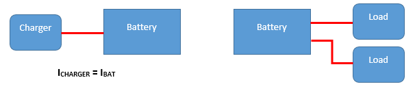
In the case of a battery-powered tool or electric vehicle, the battery is either connected to one charger and not in use, or it is in use and not charging. In this case, the output current of the charger equals the battery current and a good charger can terminate the charge when the battery is full.
In the case of a power tool or EV, there is one charger and the total charging current (i.e. battery current) is equal to the charger output current:
IBat = ICharger
The charger can regulate its output voltage and measure its output current and it has all the information it requires to terminate the charge when the battery is full.

While this diagram represents the typical installation including a lead-acid battery, multiple chargers and loads, it is totally incapable of charging the battery correctly. None of the chargers can determine when the battery is full and charging should stop because the battery current is an unknown quantity.
In the case of a marine house bank, there are (often) several chargers and loads all operating simultaneously; the battery current is the difference between the sum of all the charging currents and the sums of all the load currents:
IBat = ∑ ICharger – ∑ ILoad
We can immediately see that measuring the output current of any charger (or even all the chargers) yields no usable information whatsoever for controlling charging, because loads can rob some of this current. Yet this is what regular lead-acid charge controllers do when they measure their own output current. Many, like alternator regulators, don’t even do that and blindly apply fixed or “cooked up” charge absorption times, because the algorithm is blind and has no idea of the battery current. This kind of gear is completely inadequate in itself for charging lithium batteries, regardless of what the manufacturer claims. There are no correct charge control settings for it. The only practical way of knowing whether the battery is charging or discharging, and whether the termination current threshold has been reached, is directly measuring the battery current IBat using a dedicated sensor at the battery itself. Because knowing the battery current is so essential for charging lithium cells without damaging them, there are only two valid system topologies to control charging correctly:
- Each charge controller must have a dedicated input (like a shunt input) for sensing the battery current and terminate on charging based on a residual current condition; or
- Each charge controller must be enslaved to a “master” that controls the charging process by measuring the battery voltage and current and tells the controllers when to stop based on a residual current condition. This master is typically the Battery Management System (BMS).

If all the battery chargers are capable of measuring the battery current and perform a correct charge termination on their own, then a capable distributed charging system can be built.
We will note here that a current measurement shunt can be shared with multiple measuring devices without issues because it is an extremely low-impedance voltage source.
Lithium Battery Charge Control
From the above, we can see that obtaining correct charge termination imposes very strong constraints on equipment selection: either the charge controller must be equipped with an external current sensing input and implement residual current termination, or it must be controllable externally by a “master” using at least some kind of “remote enable” signal, and such a master must exist in the system and it must have the required charge control capability.

A battery management system (BMS) measures both the battery voltage and battery current to determine the state of the battery. There are no “chargers” any more. The charging process is supervised by the BMS, which ensures that correct charge termination takes place. The BMS controls voltage regulators and those ensure that the battery voltage doesn’t exceed the required value.
In most situations, it is necessary to use a BMS that offers one or more charge control outputs simply because charging equipment using external current sensing and a correct charge termination algorithm is not available or cannot be sourced. Using a charge control output also has other benefits because the BMS can disable charging ahead of disconnecting the chargers from the battery in case of problem, an essential aspect discussed under the subject of electrical design for lithium battery systems. The ability of arbitrarily turning off charging sources also makes it possible to prevent charging when it is unnecessary or undesirable, like when the installation is not being used, and this prevents the battery from being abused by being held at a high state of charge indefinitely. It also allows the BMS to pause charging while re-balancing the cells if necessary: if cells happen to have drifted too far apart out of balance between two full charges, there comes a point where a balancing circuit can’t handle enough current to keep up when finally recharging. If pausing charging can’t be achieved, the system is left with no other option besides tripping on a cell high voltage condition.
In some situations, we don’t need or want to charge the battery, but we would like to take advantage of available free renewable energy, because we know we will be making use of the stored energy later. Powering loads without meaningfully charging or discharging the cells is achievable by lowering the “charging” voltage below 3.37V/cell for LiFePO4 chemistry, which is the resting voltage of a fully charged cell. Because keeping cells full is detrimental and they should be allowed to discharge to some extent after a charging cycle, a reasonable practical voltage for supplying loads while preserving reserve capacity for short periods of time is 3.325V/cell, which equates to 13.3V and 26.6V for typical 12VDC and 24VDC systems respectively. This however requires an additional degree of charge control as we now either want to charge, hold, or let the battery discharge.
Whenever reserve capacity is not required, then the bank should be kept at a very low state of charge and loads can be powered by supplying current into the installation at a voltage corresponding to that low state of charge, like 3.2V/cell. This situation is encountered when shore power is available continuously and a mains “charger” is used. In this case, charging is the last thing we want and the equipment is best configured to operate as a constant voltage DC power supply. Some chargers can be persuaded to supply a desired constant output voltage by configuring identical absorption and “float” voltages and the better ones actually offer a constant voltage power supply mode. Others are simply intractable and must be thrown out. Another circumstance where capacity is not needed is when the vessel is laid up; a BMS can then maintain a very low state of charge in the bank through charge control.
This sums up the necessary and sometimes desirable ways of managing the charging process for a lithium house bank on board. The other aspect of battery management is deciding whether the battery should be charged or not, and/or how much; such strategies come with a view of preserving and extending battery life. Fully-engineered commercial solutions simply ignore it and charge the battery to full whenever possible. This maximises reserve capacity – which the end-user notices and appreciates, reduces battery life expectancy – which the end-user only discovers too late down the track, and eventually brings in more business, because it means re-purchasing the proprietary battery with integrated BMS. This is why the very high cost of these systems tends to translate more into superior performance while they last than actual value over their lifetime.
A wise system designer will ensure there are ways of keeping the cells at a low state of charge when capacity is not needed and charge the battery wisely. When energy availability is plentiful, there usually is no need to recharge to full, or the battery can be allowed to cycle much more deeply between full charges, which reduces the frequency of cycling and the time spend at a high state of charge. A battery that spends its life only as charged as it needs to be, rather than full, will last considerably longer.
Overcharging, Power Quality and Cell Destruction from Charging
The most common misconception about charging lithium batteries is believing that the State of Charge and by extension overcharging have anything to do with voltage. They don’t. A cell is being overcharged once the lithium ions are becoming depleted. The telltale that the cells are becoming full and charging must stop is reduced current acceptance, which is why using battery current for charge termination is mandatory. When a battery is being overcharged, its ability to absorb current trends towards zero and its apparent resistance to charging becomes increasingly high. The result is that the battery can no longer clamp the voltage down if it spikes. This has catastrophic consequences when the charger output is not well filtered because an overcharged battery becomes increasingly exposed to the peak ripple voltages. Eventually, the battery can no longer absorb any current at all and it is exposed to the full fluctuations in the supply voltage. If these exceed about 4.20V/cell for the LiFePO4 chemistry, the electrolyte is broken down into gaseous products and pressure starts to build up into the cells.
We sometimes see claims that charging at 3.60 or 3.65V/cell ruined a bank and caused the cells to swell, but a smooth DC voltage at that level is insufficient to decompose the electrolyte. The problem comes from overcharging and poor power quality.
The worst ripple voltage is produced by solar PWM charge controllers, followed by old-style transformer/rectifier battery chargers, which should not be associated with lithium batteries. In the case of a solar PWM charge controller, the solar array is connected and disconnected from the battery at a fixed frequency. The open-circuit voltage of a solar array charging a battery in a 12VDC installation typically reaches up to about 22V (36-cell panel). Once the battery can no longer accept enough current to keep the voltage down, every time the controller sends a pulse to the battery, the cell voltages are gradually driven towards 22 / 4 = 5.5V. If the pulse voltage reaches 4.2V, there is sufficient energy for the electrolyte decomposition reaction to take place and the cells get rapidly destroyed, even if the average battery voltage as measured by a multimeter appears acceptable.
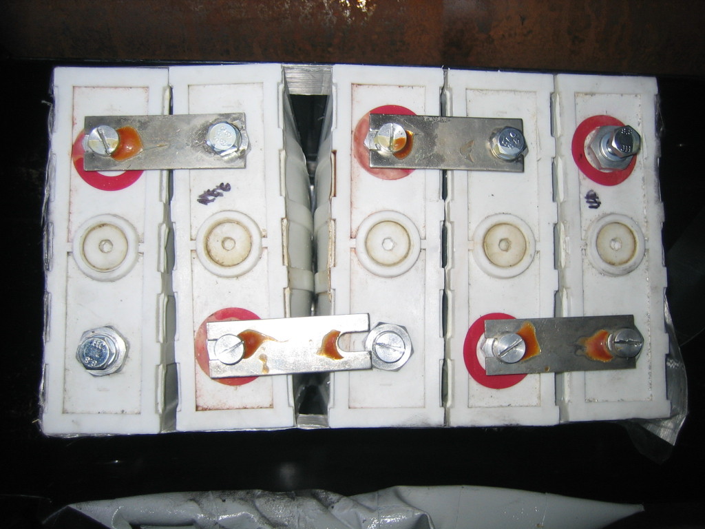
LiFePO4 cells destroyed by overcharging. The pressure in the cell casings was sufficient to push the cells apart.
Some of the power sources we use for charging batteries do not produce clean, filtered DC power, like alternators. As long as the peak ripple voltage can’t reach dangerous levels and correct charge termination always takes place, the situation is acceptable.
System Architecture and Topology
In a typical small-scale marine lead-acid battery system, multiple charge controllers follow independent algorithms and charge the battery in an approximate way while erring on the “safe” side for achieving battery life, which is overcharging it mildly. Overcharging, which causes gassing and recombination, stirs up the electrolyte and promotes voltage equalisation across the cells. This means a distributed charge control architecture which provides at best a roughly acceptable result. When it doesn’t, the battery gets damaged and the blame simply goes to whoever configured the myriad of “charge control settings” available.
In a lithium battery system, overcharging cannot be allowed to happen because it damages the cells and correct and accurate charge termination is needed. This requires an algorithm with a knowledge of both battery voltage and battery current. As common charge controllers are incapable of performing this function, they are incapable of performing charge control and this function must be implemented by the BMS. This leads to a different charge control architecture where the BMS is the only true charge controller and the slave devices only perform a voltage regulation (and sometimes power conversion) function: they really are just voltage regulators in this context because their only function is limiting the output voltage and wait for the BMS to signal the end of the charge.
As a result, the architecture and topology of lithium charging system is very different from what is typically found in lead-acid systems. However, if lead-acid batteries were being charged properly and with all due care, as they are in large stationary installations where the battery cells represent a very large investment that must last, the charge controller(s) would also feature an input for sensing the battery current, a lot of obscure programmable “charge control settings” would become pointless, and this difference would not exist. It is the result of the industry selling easy-to-install garbage equipment into a DIY marine/RV market and most of the difficulties with building good lithium battery solutions on board trace back to having to try and integrate garbage consumer-grade products. This situation has only been improving very, very slowly over many years and is still far from satisfactory.
The problems arise at the interface between the central BMS and the voltage regulators:
- Ideally, the BMS should be able to transmit the desired voltage setpoint to all the regulators. A lack of standardisation, compatible communication interfaces and product capability still makes this largely impossible. Until recently, only single-brand, proprietary systems could achieve this. Victron Energy published some details about its communication protocols and interfaces, which is very commendable, but there is a lack of commonality across products and, while remote configuration would often be possible, the required information has not been released. Too many devices are not addressable and therefore can’t be networked properly. This can currently be alleviated by plugging them into a gateway device (Cerbo GX), which implements the open CAN SMA protocol from SMA Solar Technology AG to listen to messages from a growing number of BMS units, but in this case the resulting solution is limited to other Victron products and the question of the added drain on the battery from the Cerbo GX would need to be examined closely. The adoption of CAN SMA on solar regulators, alternator regulators, chargers etc seems to be the most promising pathway forward at this point in time (2022) and developments should be watched closely. This would lead to open networked charging systems with interoperability across brands.
- The next option is accepting a lower degree of control and flexibility and configure the regulation voltages at regulator level; this we can generally do by using programmable devices, but it then leaves the matter of enabling and disabling the regulator. Some regulators feature a digital “enable” input: use it! When they don’t, problems grow because the “charger” must be either disconnected from the battery (when feasible without risking damage) or its power feed must be interrupted in order to disable it. Neither option is very attractive as both require interrupting a high power path using the like of solid-state relays, but sometimes it is possible and there is no other way.
- Short of being able to transmit the voltage regulation setpoint to the regulators, we would still like to be able to control whether they should charge or hold, i.e. supply current to the loads without charging. As most programmable charge controllers have voltage setpoints for absorption and “float”, we could achieve this quite simply using the “float” voltage setting if there was a way to force them into “float”. Unfortunately, there generally isn’t. They go into float when they feel like it and the
victiminstaller is left to play the Game of Settings to try and approximate a desired outcome without ever getting there reliably.
Besides being externally controllable by a BMS, the charging sources must also be able to cope with a battery disconnect event. A controllable charger will normally be disabled by the BMS ahead of such an event and this normally takes care of most issues. Some voltage regulators however resist just about all attempts at integration in lithium battery systems. Wind generators are notorious for this, as well as for sloppy, horrible voltage regulation and surging. Any disconnection under load usually destroys them and they must see a battery at all times in order to operate, which unfortunately defeats the strategies discussed here. They are among the worst charging devices to integrate safely and properly with lithium battery systems.
The Losing “Game of Settings”
Most of the DIY lithium installations fail to terminate charging correctly because their design and the hardware employed make them incapable of doing so. They try to hold together by relying on a precarious balance between “charging parameters” and energy consumption. A lot of the time, the battery gets overcharged to various degrees, sometimes every day. Any meaningful change in the operating conditions of the installation throws the balance out: in the absence of consumption, the battery gets slammed to 100% SOC; start the engine when the battery is already charged up and it gets abused by the alternator.
Solar charge controllers are notorious to overcharge lithium batteries. First, they initiate a new charging cycle every morning as the light comes up, so in the absence of sufficient overnight consumption, the bank cannot cycle properly. Configuring a “float” voltage low enough as discussed earlier does allow to create some kind of charge termination for sure… after a fixed absorption time, which is wrong most of the time. Many models won’t allow absorption times short enough to be even hopefully realistic, so they overcharge every time. Some units offer optional termination based on the residual (or “tail”) current as an improvement, but as they measure their own output current, they can’t tell whether the current is going to the battery or a load… This only works if consumption is zero, so let’s say that the average background consumption on board at anchor is 2A and charging should terminate when the battery charge current reduces down to 6A. We configure a tail current setting of 8A to try to account for this and terminate the charge and now it works… until the background load is suddenly higher, because the vessel is under way and a whole lot of instruments are on all the time, and from there on the cells get overcharged because the “controller” is fooled by the extra load.
The Game of Settings doesn’t work. These strategies are not solutions, only hopeful attempts at damage minimisation.
A compounding factor is the fact that people who want to install a lithium battery bank also want to reuse the gadgetry they already own. Reprogramming a typical lead-acid charging system differently, when this is possible at all, doesn’t actually lead to any solution, because it is conceptually inadequate for charging a lithium bank: it can’t possible operate the way it should.
Approximating the Solution
One of the reasons why this article has been a very long time in the making is because the only way to build an actually acceptable lithium charging system for a marine vessel was (and still is to a very large extent) by using custom-built electronics. In the past few years, this state of affairs has started to evolve very, very slowly, but it is far from being satisfactory. It leads people towards trying to approximate the solution and it nearly always falls short of the mark.
Considering that the biggest issue is the absence of correct charge termination, one approach can be giving up altogether on absorbing the battery when it is not possible to do it properly:
- at least one charging source is capable of performing a full charge with correct termination based on residual battery current every time; and
- this source (which can be the engine alternator for example) is used occasionally; and
- all the other charging sources are programmable and can be configured to skip absorption, so they just switch to “float” immediately when the absorption voltage gets hit; and
- there is nearly always a load on the installation, so the bank doesn’t get partly charged and then rested; and
- the “float” voltage can be configured low enough to ensure the battery will nearly always discharge; and
- these sources do not restart charging before the bank has been able to discharge meaningfully,
then all the “bad” chargers will perform partial charges only without leaving any memory in the cell because of the immediate subsequent discharge and the one “good” charger will reset the cell chemistry and erase any trace of memory if needed, as well as allow cell balancing to operate during absorption, whenever it is used. Such a system can hold together without tripping on cell high voltage and offer good battery life if its user has also ensured that the depth of cycling is sufficient by matching up charging capacity and battery size to the average consumption. This means coupling relatively small battery banks to good charging capacity. If the average consumption reduces too much, this fragile equilibrium will suffer and human supervision and intervention become essential at such times.
At this point, the hopeful system builder will discover that most charging sources cannot be prevented from restarting to charge whether the battery needs it or not and many cannot be controlled externally either, so in other words they simply constitute lithium battery overchargers. Most DIY systems in operation today use overchargers and the amount of damage they cause varies with the load patterns experienced by the system.
Many “charge controllers” sold with the word “lithium” in the accompanying pamphlet are simply unusable, some to the point of being purely destructive. Some of the most infamous examples are the “lithium” versions of the Genasun GV-5 / GV-10 solar MPPT controllers: these little marvels of engineering and efficiency respectively deliver up to 5A and 10A at a steady 14.2V output… forever! There is no way to adjust anything and no way to turn them off without seriously hacking the circuit boards. These are the best lithium plating controllers on the market. Genasun exited the lithium arena many years ago now, but they keep marketing some of the garbage technology that was destroying their batteries.
Charging lithium batteries requires precise control because no overcharging can be tolerated. If the topology of the charging system is incorrect, the system is not capable of charging a battery correctly and no amount of “programming” will ever change that.
We need good charging equipment and that is:
- Charge controllers with a battery current measurement input and a residual current termination algorithm; or
- Programmable voltage regulators interfaced to a BMS using an external enable input and (ideally) another input to switch them to a lower holding voltage when the charge is complete; or
- Voltage regulators we can control with a BMS by sending a setpoint via a digital bus.
In all cases, we need regulators that don’t engage in rogue, arbitrary recharging for no reason, so we can allow battery banks to discharge and keep them at a low state of charge when this is desirable.
Hi Eric, very tough matter, thank for the explanation. I have a question though. Say I measure amps at the LiFePO4 battery and use that to terminate charging @ 0.033C. Say I’m charging with solar so the charging amps depends on the sunlight and it might be only a few amps. How can I distinguish that from 0.033C charge current? As far as I can tell both situations seem the same!
Rob,
You seem to be referring to the case where the solar charging current is below 0.033C. In this case, 100% SOC is effectively reached at a voltage lower than the specified termination voltage for 0.033C, see the example provided in the text. It is not the same and only a good BMS programmed to deliver a smart charge termination can help you there.
Kind regards,
Eric
Hi Eric,
thanks for your detailed articles.
A have 2 victron smart lithium batteries in series for 25.6V battery, in a solar system that is cycled down to 70% every day (sometimes down to 40% but rarely). I have monitored this for almost 18 months with the Victron VRM system and am pretty familiar with its behaviour.
As you may know, the Victron active balancing on the batteries only works above 28V (3.50V/cell) – so I currently have the system configured to charge to 28.4V every four days for 1 hour to achieve cell balancing (if venus could be configured to use the tail current from the BMV as its switch between bulk/float, I’d use that instead of a fixed time, but at the moment thats not possible).
The rest of the time the controllers switch to float straight away.
Victron recommend a float voltage of 27V (3.375V/cell) – this is in the “charging” voltage range. This is evidenced by the batteries continuing to take current after the fast switch from bulk to float.
I have found that setting the float voltage to 26.7V (3.33V/cell) stops this – i.e. the batteries don’t accept any current.
Would be interested in your thoughts…..
Jason,
The problem comes from the fact that the people at Victron have been marketing lithium batteries for quite some time, but they still don’t fully understand the technology. 3.375V/cell is excessive as a “float” voltage. Your installation is cycling regularly and it is fortunate, because this otherwise shortens the life of the batteries by holding them full as if they were lead-acid. It is unfortunate, but when companies are in the business of selling batteries, there is an immediate conflict of interest between maximising life for the end-user and maximising revenue.
Kind regards,
Eric
Just to share my experience:
I have been using my small homebrew LFP installation now for a couple of seasons (4 months yearly).
It consists of an unmodified LA charger and a standard 125A Yanmar alternator, both connected to charge the LA starter battery. The LFP consists of four 100 Ah Winston cells.
Separate charge and load buses are used.
The LFP is connected to the LA battery trough my custom BMS that limits the LFP voltage to 14.00 Volts and terminates the charge at 0.02 C.
The BMS pass element consists of 4 parallell FETs that can take 500 Amps of current.
These are used as variable resistors to limit the charge voltage, thus avoiding any possible PWM current spikes.
At 14 Volts the charge currents have already dropped so much that the power loss in the FETs is small. The LA chargers peak out at 14.4 Volts, keeping the power loss in the FETs down.
The BMS restarts the charging when the LFP voltage has dropped below 13.3 Volts.
The BMS pass element FET diodes allow for current to pass back to the starter battery, giving some support for starting the diesel. This setup also prevents the starter battery self discharge to too low levels. And it ensures a voltage drop below 13.3 Volts when the engine starts, thus starting again the LFP charge cycle.
The load bus is connected to the LFP battery.
The load bus is controlled by the BMS which disconnects when the LFP voltage falls below 12.5 Volts.
The solar panel is connected in such a away that it only charges the LFP up to 13.3 Volts.
That means I can have a fairly full house battery when I leave for the next trip, and have the solar panel support when sailing.
The alternator charges the LFP to 100% as I motor out of the harbour.
The highest alternator charging currents are limited in practice by the standard alternator and by the voltage losses in the cabling. An empty battery is charged initially by 60+ Amps for a while, but mostly the charge current stays below a safe 30 Amps (0.3C).
There is no cell balancing circuit or cell voltage supervision used. Since nothing is connected to intermediate cells, there are no circuits there to cause potential problems. Cell balance is checked manually now and then.
A 100 Ah LFP house battery has been quite adequate in my case. My battery usage is maybe 30 Ah per day. The solar panel supplies 10 Ah on good day.
Mikael,
It is always interesting when someone engineers something new instead of plugging various building blocks together, so thank you for taking the time to describe it.
The few comments I would make are:
1/ You must have cell voltage monitoring to have a BMS. This is NOT a BMS! It is a kind of charge regulator basically. Making battery protection decisions based on overall battery voltage is not acceptable with lithium cells and the more cells in series the worse it gets.
2/ Since you are not using PWM drive for your FETs, you are operating them in their linear region. They might be good for 125A each when the gate is fully enhanced and the device is mounted on a large heatsink and operating at peak temperature, but the thermal dissipation limit will be reached well before that in the linear region. MOSFETs also have a negative temperature coefficient, so if one starts running hotter than the others, it will carry more current, get even hotter and eventually fail. This kind of application requires very careful design and construction to be reliable.
3/ You write that “at 14 Volts the charge currents have already dropped so much that the power loss in the FETs is small”, but this is only because of the characteristics of your wiring/charging system. If the absorption voltage is 14V, it is reached at full current when the charging system is capable and the current starts reducing from this point on. The gear needs to be able to handle more than the worst-case scenario or it will fail, sooner or later. If the lead-acid battery was some modern AGM type charged in cold conditions with temperature compensation, the input voltage could easily exceed 15V.
4/ When reversed-biased, a MOSFET behaves like a conducting diode and will overheat very quickly if a lot of current passes through, unless it is turned on (and then it conducts both ways). As a result, if the starting battery is under heavy load, your only option is turning the FETs on or watching them go up in smoke… You can’t prevent the engine circuit from completely draining the house battery either, which defeats the concept of having two batteries. In order to implement a bidirectional switch with MOSFETs, you need twice as many transistors wired in a back-to-back configuration.
Kind regards,
Eric
The problem with driving multiple FETs in linear mode is that they require different gate voltages to get balanced current. I built a linear supply using 8 parallel FETs. The trick is that there is one master FET driven by the regulator, all FETs have small drain resistors for current sensing and the other 7 gates are individually driven by fast OpAmps so they carry the same current as the master FET.
I have read your articles and learned a lot but I have a question about charging from the alternator.
How to terminate the charging as I haven’t seen one single BMS performing a correct absorption phase.
Is it OK to perform “bulk”-termination for 2-3 month before a complete charging process takes place?
You have several times pointed out that the cells should not sit around fully charged for a period of time.
How long? 1-2 days, a week, 14 days etc.
Best Regards
Gösta
Gösta,
In order to trigger memory effects, you need to charge partially and then let the cells rest. If you do a partial charge followed by an immediate discharge, it doesn’t matter. Problems really develop when you always stop charging at the same place and don’t discharge afterwards. You can terminate at the end of the bulk phase for as long as you want, provided there is a load on afterwards.
You may run into cell balance problems if you don’t recharge to full often enough and the cells are drifting apart over time. This could be the limit. Some packs are good at staying balanced, others not at all.
The cells must not be left at a high state of charge. You can answer your own question by asking yourself how much accelerated aging you want to cause. LiFePO4 is not a good chemistry for standby capacity service.
Kind regards,
Eric
Hi Eric,
I have installed 4 Winston cells in my RV. When I return from a trip, I discharge my Battery down to 12,8 V. Then I set my triple Votronic charger to 12,8 V constant voltage and connect it to the mains.
The charger combines solar + AC + Generator into a single charger. All loads remain connected, but most of them are off anyhow. As a result my Battery is kept at 12,8 Volt at all times, with a maximum output current of 25 A. In wintertime I can run my heater to keep the temperature above freezing.
Any comments?
Cheers Hans
Hans,
This type of arrangement allows the battery to discharge quite significantly for storage when its capacity is not needed. It is very good for battery life and much better than cycling unnecessarily.
Kind regards,
Eric
Hi Eric,
thanks for your confirmation!
Very interesting your explanation of the correct termination current for a 100% charge!!
Just to make sure, that I unterstand your table in a correct manner:
Charging with 3.5 V CV means that the Voltage drop at the cell impedance is 130 mV above the OCV of 3.37 V at 100% SOC. For a 100 Ah cell, the termination current would be 0.015 C = 1.5 A.
I conclude, that the actual DC cell impedance is 130 mV / 1.5 A = 87 mOhm at 100% SOC.
I assume, that the DC cell impedance drops to much lower values at lower SOC values.
Any idea about the function of the DC impedance over SOC?
Servus from Bavaria
Hans
Hans,
Yes, you can look at it this way, but since we are dealing with DC current only, there is no reactance component involved and the impedance is the internal resistance.
The internal resistance of a cell is initially influenced by the manufacturing process and then it is temperature-dependent and increases throughout the life of the cell as it ages, so it is not something that can be quantified and relied upon without actually measuring it dynamically on the battery in service. It makes it quite problematic to use for practical purposes. It is used in some advanced BMS algorithms for estimating remaining capacity at a given load based on the low voltage cut-off threshold.
There are plots of internal resistance vs SoC in the literature and they sometimes show these relations with temperature and cell health.
Here, the discussion about termination is intended to address the real-world issue of overcharging when the available charging current is below the termination current, which can happen quite easily with solar under very poor conditions.
Kind regards,
Eric
Hi Eric
Thanks for sharing sharing this interesting article. I can tell you put effort it to making it clear and thorough.
I have question about this:
“Lower voltages will fail to charge it extremely quickly and voltage cannot be used as a mean to control the outcome of charging as a result and absorption voltage alone has no bearing whatsoever on the final state of charge reached.”
Is the absorption voltage an upper limit on the battery voltage?
If so, would setting a low-enough absorption voltage effectively limit the state of charge?
If so, does this mean that the absorption voltage can have a bearing on the final state of charge reached?
I’m not sure if this is a semantics issue or if I am misunderstanding the physics. I am new to these concepts.
Thanks,
Eric Bakula-Davis
Eric,
The absorption voltage is the highest voltage the battery is allowed to reach during its charging cycle. Setting a very low absorption voltage makes charging ineffective and can certainly prevent full recharging, but the state of charge reached is extremely sensitive to both the voltage and the length of time (i.e. absorption time) this voltage is maintained for, so it is not a practical way of limiting charging.
Kind regards,
Eric
Thanks Eric. That clears it up for me.
Thanks for the valuable information about lithium technology.
When Lifepo4 batteries are used as a service battery on a boat, we know that installing a current-limiting DC-DC charger on the charging line with the alternator prevents the alternator from overheating as well as charging the lithium battery with a safe charging current. While the DC-DC charger used is in operation, I understood that the lithium battery charge could not be completed properly, since there is also the consumption of the working devices, and the charging cycle designed according to lead-acid batteries, always trying to keep the battery full, prevents this. This can be a problem on long engine journeys.
I looked for a way to at least protect my existing alternator from the sudden HVCutoff action of the lithium battery. I deliberately disconnected one of the brushes that constantly feed the rotor warning of the alternator and soldered two wires to the cut points and pulled it out of the alternator. When I disconnect the terminals while the alternator is running, the charge is cut off. When these terminals are brought into contact again, the charge continues from where it left off.
With a small voltage sensitive relay, I can safely switch the alternator charge on and off depending on the system voltage level. Can you suggest a safe charge cut-off voltage that will ensure the longest life of Lifepo4 batteries?
Volkan,
No, you can’t do that simply because a BMS will trip the battery based on the voltage of any single cell, not the overall battery voltage. The BMS must supply the signal to stop charging before tripping the battery. If you can’t do that, your only option is diverting the current to a lead-acid battery.
Interrupting the field is the way to disable an alternator indeed. Solutions that don’t involve running the alternator current through electronics are more efficient and reliable.
All the best,
Eric
I have read all of your posts – excellent. One thing you don’t discuss a lot is balancing between batteries in a parallel battery bank. I know the recommendation is bus bars with equal length wires so that all paralleled batteries have exact same charge/discharge resistance and voltages. But it seems like that ideal perfect scenario may not always be reached on boats – where a lot of non-ideal compromises are involved.
I’m using diagonal parallel wiring, which should be pretty balanced, but battery 1 (of 4) still delivers more discharge current and gets charged to full slightly before the other 3. They’re 4 x 100 Ah 12v Kilovault’s. The charge recommendation is 14.1v for only 2 minutes or 2a tail current per battery (8a total for me). The probability of all batteries hitting exactly 14.1 and 2a tail at precisely the same time (or within 2 minutes) seems to be quite improbable so far.
In that case, what would you recommend? I can terminate charging as soon as the parallel bank hits 14.1 for 2 minutes, but batteries 2 thru 4 are still accepting 8 to 15a each. Battery 1 is accepting only 1-2a. So if I terminate then it ensures battery 1 doesn’t get overcharged, but in the long run I’m worried the other batteries may not get top balanced since they’re getting slightly undercharged (to like 99.5% SOC instead of 100%). Maybe I should continue at 14.1 for 20-30 min even though the manufacturer recommendation is ideally 2 – 6 min?
Patrick,
This is because the focus of this series of articles is on building battery banks from cells, not from packaged batteries like you have done, but your point is interesting nevertheless and I precisely intend to discuss in more detail the “parallel strings” configuration in the other article about assembling battery banks.
Parallel strings is an idea that sounds great in terms of redundancy and safety, but it also comes with more issues than one may expect, as you have discovered. This is because each battery string is an entity with its own performance and ageing characteristics and this means that a common charging strategy can’t work optimally across multiple strings. When charging at high currents in particular, differences of a few milliohms in the interconnects or cell internal resistances are enough to imbalance the charging currents and completely upset the time to charge termination.
Termination still needs to occur correctly and so each battery should be individually disconnected from the charging sources as it reaches “full”. In such a “parallel strings” configuration, there is one BMS per string and this BMS should be entitled to terminate the charge…
When you drop packaged batteries in an installation and wire them in parallel for more capacity, you are trying to simplify the situation and largely ignore battery management, but it creates its own set of issues. Charge termination is not the only one of them, it also creates more complex failure modes with potential cascaded failures that largely negate the “high reliability” argument.
Kind regards,
Eric
Could you please show the math for determining the termination current based on cell voltage?
Russell,
Using:
V_abs_m = cell manufacturer’s absorption voltage (usually 3.65V)
I_term_m = cell manufacturer’s termination current (0.033C to 0.05C typically, or use it expressed in amps alternatively)
V_abs = actual absorption voltage (valid values are greater or equal to 3.37V)
I_term = actual termination current
We can write:
I_term = I_term_m * (V_abs – 3.37) / (V_abs_m – 3.37)
Much appreciated.
Thanks!
If I understand correctly the conceptual linchpin is the full resiting voltage of an LFP cell being 3.37VDC.
How did you determine this value?
Is it universal across LFP cells?
It is specific to the LiFePO4 chemistry.
I was very interested to see your graph with the overcharge area on the bottom right. I’ve been under the impression that it was impossible to overcharge batteries if I stick to 4.2V for ternary lithium or 3.6V for LFP.
What degree of damage could I expect if I hold the battery charging at 3.6V for longer than the table stipulates? I rescued a decade-old, 7s, nominally 40Ah LFP battery that was destined for the landfill and I’m running it through some charge/discharge cycles. If I respect the 0.05C cutoff that means terminating charge at 2A, but cycling it that way I measured only 30Ah of cyclable capacity. However if I continue the absorption at 3.60V down to 0.2A (so 0.005C, or 10 times smaller tail amps), I get an additional 8Ah of charging capacity. Does this mean I’m damaging the battery, or would my case be an exception due to the battery’s age and presumably level of degradation excusing the longer absorption?
I also have two simple questions if I may. For manually charging a standalone battery with a CC/CV power supply and monitored against over-voltage with an active-balance BMS within the battery, what CV setting do you recommend – 3.5V or 3.6V?
And lastly, should the charge current be limited at very low states of charge (say <10%) or can 0.5C be sustained right away, starting from 0% charge (i.e. 2.65V/cell)?
Luke,
You will most definitely overcharge the battery if you hold the voltage up past the termination point. What happens is that all the free lithium gets displaced and the current drops down to zero. Once the cathode can’t absorb any more Li+ ions, they start plating what they can inside the cells and the result is irreversible.
The termination voltage and current varies between cells, but it is usually in the range of 0.02-0.05C for prismatic cells at least. Your cells could be different, the only way to know would be getting the specification from the cell manufacturer. In my experience, the cells develop higher internal resistance as they age, but the charge termination condition doesn’t change. I have a 9-year old LiFePO4 battery in service here. It has lost some capacity and the voltage sags more under load, but trying to charge it more forcefully achieves virtually nothing besides stressing it. I tested that a few years ago to see if I could somehow recover the lost capacity in case it was due to memory effect. It wasn’t.
I have never found any reason to charge LiFePO4 cells using more than 3.50V/cell in normal service. Unfortunately, if you use a BMS that won’t balance until the cell voltage is significantly higher, then it will allow cell imbalance to develop further before taking action and (usually) also fail to fully rebalance, but this is not automatically a significant operational issue and you can perform the occasional charge cycle (say once a year) up to a higher voltage at low current to fully rebalance the cells if desired. It is always better for the cells not to be exposed to unnecessarily high voltages as it causes them to age faster.
All the data I have seen indicates that the only situation where the nominal charge rate must be reduced is low temperature. Low temperature limits the rate of diffusion of the Li+ ions into the cathode and exceeding that rate also leads to lithium plating. The state of charge of the cell doesn’t matter.
Kind regards,
Eric
Hi Eric,
Many thanks for replying. I’m afraid that since this battery was recovered by the previous owner from a solar-powered buoy I don’t have a datasheet or any info to speak of, so I’m trying to discover the cell capabilities myself. I recently fitted a JK BMS with a 1 Amp active balancing, and I’ve sorted most of the settings but still playing with the balance start voltage. The default is 3V but I’m thinking to raise it to 3.4 or 3.5V so it won’t undo the top balance with each discharge cycle as one of the cells is much weaker than the rest (by about 5-10Ah on this 40Ah pack) so ends up at a lower voltage than the rest of the pack consistently.
Just to make sure I understand – if 0.05C @3.65V corresponds to a termination current of 2A, and I keep going to say 1A @3.65V (not zero amps) would it still have caused damage then – despite not continuing until current is zero? I take it then that if current flow is a result of lithium ion flow, could the current I’m seeing be caused by the ions forming the plating instead of intercalating into the cathode?
I’m a bit curious how far this can be pushed because it seems the 0.05C is an arbitrary value chosen to have some factor of safety. On healthy cells like my new 280Ah 4s pack, there’s not much to be gained pushing this number, but on my mystery 40Ah pack there’s an almost 25% increase in charge capacity by terminating at 0.005C instead of 0.05C. I’ve just finished doing that to manually top-balance the seven cells and it took 9 hours of absorbtion for each cell (using a hobby charger at 3.60V). Reading your comment now I see I might have ended up making things worse by letting the charge go on that long – but I will do an instrumented discharge test soon to see whether real capacity has increased or decreased. I’m doing this more to learn than out of a particular need to keep using this pack.
Some weeks ago I left the pack for 7 days at 2.000V per cell (using an external supply and keeping the BMS balancing the cells) because I read a paper than said this will recover some capacity in LFP cells that had been part-cycled all their life. Ultimately it didn’t improve their capacity nor did it reduce it so at least that’s one experiment done. Now trying other ideas (the extended absorbtion for perfect top-balance being one of them).
If you have any other ideas for recovering lost capacity I’m keen to hear them!
Luke,
The termination condition is not arbitrary, it is manufacturer-specified. If you don’t know what the cells are, then you won’t know what it is.
A 40Ah pack with a weak 30Ah cell is a 30Ah pack.
Balancing can only be done either at the top, or at the bottom. In practice, it is nearly always done at the top. You can’t start balancing until cell voltages begin to visibly diverge. This doesn’t happen below at least 3.4V/cell for LiFePO4 and more like 3.45V/cell.
Capacity loss from memory effect has nothing to do with part-cycling as such, it originates from incomplete charging followed by a period of rest. It makes cells harder and harder to recharge because the voltage rises to early during the charge cycle. I am not aware of low-voltage methods for recovery from memory effect. LiFePO4 cells should not be discharged below 2.5V/cell.
Lithium cells of unknown origin and with a dubious history can be dangerous. They can ignite quite unexpectedly, especially during charging.
Hi Eric,
I am supporting a Student at the Bundeswehr University in Munich. He is working on His doctoral thesis.
Can we use parts of your papers and comments, if we clearly identify the source?
Thank you for an answer,
Regards Hans