
Last Updated on 22 February 2020 by Eric Bretscher
This article is part of a series dealing with building best-in-class lithium battery systems from bare cells, primarily for marine use, but a lot of this material finds relevance for low-voltage off-grid systems as well.
Integrating a lithium battery bank on board a vessel introduces a few additional constraints and challenges that don’t exist with lead-acid batteries. Let’s consider two key statements:
A key difference between a lead-acid and a lithium battery is that the former can be damaged safely
While this may come across as provocative, it is nevertheless very true. Overcharging or flattening of a lead-acid battery is detrimental to its life. That’s about it. A lithium battery quickly gets totally destroyed and becomes a fire risk in the same circumstances.
Another main difference between a lead-acid and a lithium electrical system is that, in the second instance, the battery may become entirely disconnected from the installation, which can result in considerable damage
Protecting a lithium battery from damage may ultimately require isolating it from the system following a dangerous adverse event. A charge regulation failure or a complete discharge, for example, are such events. Unfortunately, there tend to be charging sources in marine DC electrical systems that are typically not designed to operate or cope without a battery in circuit in most instances: disconnecting the battery has a strong potential for causing malfunctions and sometimes considerable and very expensive collateral damage.
The battery is the base load in the charging system and is required to prevent the voltage from spiking up, sometimes considerably; many charge regulators cannot function or regulate properly without it.
In this article, we will discuss some avenues and options to design systems taking care of these aspects.
Disclaimer
A good understanding of DC electrical systems is needed to build and commission a lithium battery installation. This article is aimed at guiding the process, but it is not a simple blind recipe for anyone to follow.
The information provided here is hopefully thorough and extensive. It reflects the knowledge I have accumulated building some of these systems. There is no guarantee that it will not change or grow over time. It is certainly not sufficient or intended to turn a novice into an electrical engineer either. You are welcome to use it to build a system, but at your own risk and responsibility.
Basic Electrical System Design for Lithium
Due to the above considerations, the electrical system on board needs to conform with a model that allows battery disconnection without creating additional problems. In nearly all instances, alterations need to be made to the existing installation before a lithium battery bank can be considered. This assessment should take place before anything else.
There are absolutely no issues with electrical consumers on board; the voltage out of a lithium battery bank not only is within the range of what is experienced with lead-acid systems, but also exhibits less variation. A typical lead-acid system operates between 11.5V and 14.4V (less for gel cells). While the practical voltage range of a lithium system extends from 12.0V to 14.2V at the very most, the bulk of the cycling takes place between 13.0V and 13.4V only.
The challenge resides with charging sources and the risk of seeing them being disconnected, including under load, or even worse, directly feeding into the boat’s electrical system without a battery present.
Dual DC Bus Systems
Dual DC bus systems represent the optimal solution in reliability, resilience and functionality with lithium batteries:
- Power on board is not lost if an issue is detected with a cell reading excessive voltage. This can happen if a charger regulates poorly, cell imbalance is developing, or there is a system setup issue.
- A low-voltage disconnect doesn’t compromise recharging and the system has a chance to recover by itself.
This makes the dual DC bus topology very desirable on board marine vessels, but it also comes with higher engineering requirements.
The conversion of an existing installation to use a lithium battery bank with a dual bus system first entails segregating charging sources from electrical loads. Skipping this step is not really possible unless another (lead-acid) battery remains in circuit after the lithium bank is disconnected.
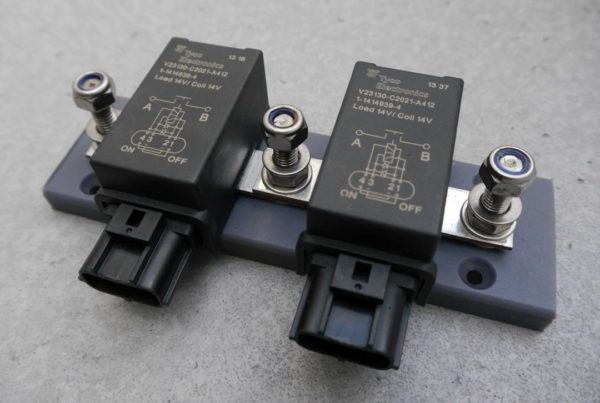
Twin battery disconnectors are at the heart of all dual DC bus lithium systems. Those are top-quality Tyco Electronics latching relays that offer zero standby consumption and a 260A continuous current capacity. The battery bank connects on the middle post, while the load and charge DC buses tie on the sides.
Creating a separate charge bus and load bus normally requires some rework of the heavy current cabling. Choosing a judicious location for the disconnector relays goes a long way towards minimising the impact of the changes. Electrical distribution is normally either carried out close to the battery compartment, or a feeder cable runs from the batteries to a distribution panel where the main positive and negative busbars are located.
Occasionally, marine electrical systems conform to another topology known as a Rat’s Nest. Those need to be pulled out before any further considerations
In essence, the positive busbar must be duplicated to separate charging sources from loads; the negative busbar normally stays as it is. The battery disconnectors are inserted close to this point to tie the bank into the system and any feeder cables normally remain unaffected.
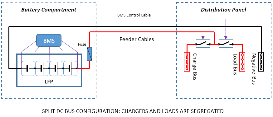
The split DC bus configuration is the gold standard in terms of reliability and functionality for lithium battery installations. It is the preferred pathway for engineering elaborate lithium-only systems and for critical applications as it allows for specific and optimal responses to both excessive charge and discharge situations. Achieving this result requires capable equipment and good system design.
Controlling a dual DC bus system requires a BMS offering suitable outputs: this is not commonly found on solutions intended for electric vehicle (EV) conversions, which tend to rely on a single “disconnect all” contactor.
Attempting to build a dual bus system with an inadequate BMS all too often results in installations where both buses can (and therefore will, sooner or later) end up connected with no battery to charge; at this point, an unregulated charging voltage usually gets fed straight through into the boat’s electrical system, leading to a memorably expensive wholesale fry up. The ultimate in terms of the depth of thoughts afforded by the incident is when it happens at sea.
Key Challenges with Dual DC Bus Lithium Systems
It is fair to say that, today, a majority of DIY dual DC bus lithium systems contain critical design flaws their owners are often unaware of, or have decided to ignore because they could not solve them properly. This is often related to the use of some junk-grade or unsuitable BMS solution, carefully selected for no other reason that others have used it, coupled with a lack of design analysis.
A system is not good because it works, it is only good if it can’t malfunction or fail under any unusual circumstances
Dual DC bus systems come with two challenges associated with the potential disconnection under load of the charge bus or the load bus. A charge bus disconnect event is typically associated with a high-voltage event, while the load bus normally drops out due to an under-voltage situation at the battery.
Issues Associated with a Charge Bus Disconnect and Possible Solutions
In case of a high-voltage event causing a charge bus disconnection, charging sources can end up:
- Disconnected under load, which can destroy some charging devices by causing their output voltage to spike; and
- Subsequently linked together with no battery to charge, which can also result in damage due to excessive voltages for some devices. Many charge controllers require the presence of a large capacitive load (the battery) to operate correctly.
These two situations need to be analysed carefully and mitigated if required.
Typical examples:
- A simple PWM solar charge controller switches the panels on and off rapidly to keep the battery voltage at a setpoint. The voltage varies very little because the battery absorbs the current while the panels are turned on. If the battery is removed, the open-circuit voltage of the panels is directly transferred to the output and injected into the charge bus: this means about 22V at times with the standard 36-cell panels used in 12V nominal installations.
While this doesn’t really matter in itself and the controller can always take it, if other charging devices are also connected to the charge bus, they suddenly get exposed to that voltage that may prove excessive. - Many simple wind generators can be disconnected under load without getting damaged (as long as they don’t reach excessive speeds afterwards), but a very significant voltage spike can result, high enough to damage other electronic charge controllers that would happen to share the charge bus.
High voltages also keep being produced at the output afterwards if the unit spins up. This is generally completely unacceptable. - Some modern wind generators can’t be disconnected at all under load, or their charge controller will be destroyed by the resulting voltage surge.
- Some, but not all, MPPT charge controllers can fail from an output voltage spike if disconnected under (heavy) load. Good quality units use buck stages implementing cycle-by-cycle limiting and can in fact regulate their output even under no load.
- Alternators nearly always fail with considerable damage to the rectifiers and regulator if disconnected under load. Interrupting the current causes a collapse of the magnetic field in the stator, which induces an intense surge, sometimes in excess of 100V.
The best and the simplest avenue, by far, would be using charging equipment that can be disconnected under load without issues and won’t output wildly unregulated voltages if there is no battery to charge. Unfortunately, this is not always practical, like in the case of alternators, or economics can favour trying to keep pre-existing gear: this is not always feasible, for a number of reasons, and can considerably increase the cost of a system conversion from lead-acid to lithium-ion.
Typical solutions to address these problems fall into three categories.
Disabling the Device in Advance
This involves turning off the charging device before it gets disconnected:
- Alternators can be disabled by interrupting the field circuit with a relay.
- Shore power chargers can be disconnected on the mains side.
- Wind generators often need to be diverted into a dump load or a short-circuit, which stops them.
- If concerns exist with solar systems, disconnecting the panels before the charge controller is an effective measure and normally always safe to do.
- Many externally-regulated wind generators are best disconnected (and short-circuited) before the charge controller as well.
In all cases, powering a relay or other disconnection device to disable a charging source is completely unacceptable. These systems must be fail-safe and not charge by default in the absence of control signal, so disabled charging sources can’t restart producing power after the battery has been disconnected and an additional layer of protection is created. This requires – for example – using relays with normally open (NO) contacts or bistable latching relays, so even a loss of control power can’t lead to a reconnection.
The best is often using fail-safe solid-state switching devices to minimise the current consumption while held on and maximise reliability.
In order to implement an advanced disconnection scheme, the BMS must support it and provide an adequate signal to act upon at least a fraction of a second before the DC charge bus gets isolated.
This can take the form of a “OK to charge” control signal and/or some kind of dedicated “charger enable” output, which would both get turned off long before a high-voltage (HV) protection event occurs.
Here again, junk-grade BMS products typically never offer such functionality and are therefore completely unsuitable to build such systems.
Individual Disconnection
If damage to other charge controllers is the main concern, disconnecting a device on its own is effective. This equates to giving it its own charge bus and disconnector. This can work very well for some unregulated wind generators, which are notorious for producing voltage surges and very high open-circuit voltages. Units featuring external charge controllers (in contrast with those equipped with built-in regulators) can be disabled by intervening upstream of the controller.
The drawback is the cost of an additional disconnector.
Absorbing/Deflecting the Surge
Another very effective option is ensuring that the current has somewhere to go following a disconnection: the output of a charge controller can be split over an isolator (diodes) and shared between the lead-acid starting battery and the lithium battery charge bus.
In this case, the presence of the lead-acid starting battery becomes essential to the safe operation of the system.
Not all charge controllers accept being wired this way however, because it effectively “hides” the battery voltage until charging begins. Some controllers draw on the battery to power themselves and operate in standby before starting to charge. Many wind generators fall into this category and simply refuse to operate when cabled this way.
More relevant information can be found further below under charge splitting, because the strategy can be, partially or wholly, applied to the charge bus of a dual bus system.
Issues Associated with a Load Bus Disconnect and Possible Solutions
Disconnecting the load bus presents no hazards at all as long as all loads connected are resistive and/or capacitive in nature. Loads falling outside this definition are inductive and therefore include electromagnetic devices like coils, motors and solenoids. The disconnection of a powered inductive load results in a reverse (i.e. negative) voltage spike (also known as back-EMF) produced by the collapsing magnetic field. The amount of energy released is proportional to the square of the intensity of the field, so the primary offenders are high-current devices like winches, windlasses or starter motors.
When the load bus is disconnected from the battery to stop further discharge, any energy surge released in the load circuit will potentiall reach all connected equipment on board from lights to electronics and these will be exposed to a brief, but possibly intense reverse-voltage pulse. A lot of marine electrical equipment is protected against reverse polarity connection and, up to a point, voltage surges, but the back-EMF from a large DC motor tripped under heavy load still has the potential to take out a lot of equipment on board.
Back-EMF Suppression
Suppression involves shorting out the spike at the source and it is very commonly implemented for small coils by the addition of a free-wheeling diode. A free-wheeling diode is wired to conduct from the negative towards the positive and therefore does nothing (blocks any current) in normal operation, but it clamps out the negative voltage spike to a value below 1V typically.
Suppression is best implemented as close as possible to the source by adding a diode across the terminals of the offending winding, but a limit exists to the amount of energy a diode can take in a pulse without getting destroyed. This energy is equal to W = 0.5 x L x I 2, where L is the inductance of the motor or coil and I is the current at the time of the disconnection and, as large motors are significantly inductive and the energy increases with the square of the current, this approach is only really practical for small loads like relay coils or a fridge compressor DC motor due to the cost of very large diodes.
Disabling the Device in Advance
Disabling the device while the battery is still in circuit is here again a sensible and highly effective solution. It is best implemented as a low-voltage disconnect of the control circuit (i.e. control solenoid etc), which is low-power and low-current and therefore doesn’t require any high-capacity equipment.
This preventative action also has the advantage of potentially avoiding a low-voltage disconnect under high load with a general loss of power on board. While new, fresh, lithium cells have very low internal resistance and the voltage doesn’t sag much even under heavy loads, it increases over time and older installations become more susceptible to experiencing low-voltage disconnects under heavy loads when the cells are at a low state of charge.
Care must be taken to ensure that that this early action will always precede the disconnection of the load bus and the best and most reliable way to achieve this is getting the BMS itself to supply this signal. This eliminate potential conflicts between the reaction time of an independent low-voltage disconnect device and the BMS dropping the load bus in the event of a sudden and significant voltage drop.
Voltage Sensing
As long as a power source only charges the lithium bank, the reference voltage can normally be obtained from the bank.
The alternative is getting it from the DC charge busbar, which is the same, but upstream of the feed line and disconnector. The benefit is that it keeps reflecting the charger output voltage after a disconnection and can prevent over-voltage on the charge bus; the drawback is that it ignores the losses in the feeder cable and disconnector relay.
Many charging devices fall back on regulating their own output in the absence of a signal at the voltage sensing input, but this usually needs to be tested on vase-by-case basis if the installation is going to rely on it for proper operation.
These two strategies can be mixed and matched as required by charging devices, but the analysis needs to be carried out.
If a charge splitting strategy is used, then the corresponding guidelines apply to the chargers featuring a split output.
Simplistic Alternatives to the Dual DC Bus Topology
Building and commissioning a dual DC bus system can be demanding. It requires a good understanding of the behaviour and capabilities of the equipment used on board and some kind of “what-if” analysis must be carried out to ensure that simple unusual events are not going to result in serious malfunctions.
For these reasons, there appears to be no shortage of dangerous and irresponsible advice to be found under the KISS moniker when it comes to building lithium battery banks and installations. Let’s just say that, provided the cells have first been balanced, it always “works” – until something suddenly goes very wrong. Badly engineered lithium battery systems are still causing enormous amounts of electrical damage on board vessels, which typically doesn’t get reported back. I do hear about those however, quite regularly.
System design doesn’t lend itself to browsing around and averaging; it needs to be consistent and robust
Here, we will try and explore a couple of actually valid avenues to “simplify” the construction of a lithium system without creating additional risks.
The simplest way of resolving the issue of the disappearance of the battery in the electrical system following a safety disconnect event is… ensuring that a battery remains afterwards.
Two examples of simplistic, but safe and functional, topologies are provided below. In each case, we deflect and negate the problems instead of eliminating them at the source. While these schemes can easily be implemented successfully, they remain workarounds with some drawbacks and limitations.
There is no simplification down to the point of just dropping some lithium battery cells in a battery box
Regardless of the system design retained, all the charging voltages still need to be adjusted in order to stay clear of over-voltage problems at cell level and due care still needs to be taken not to overcharge the lithium cells.
The new battery also needs to be protected just the same, because of its different electrochemical nature.
Alternative 1 – Lead-Lithium Hybrid Bank
The simplest way of resolving all the challenges mentioned at the beginning of this article is running the lithium bank in parallel with some standard lead-acid capacity. If any issue arises with cell voltages or temperatures, the lithium bank can be disconnected and the installation will revert to a simple lead-acid system. In some instances, this lead-acid capacity could get damaged or destroyed if the event that resulted in the disconnection of the lithium cells was severe, like an alternator regulation failure.
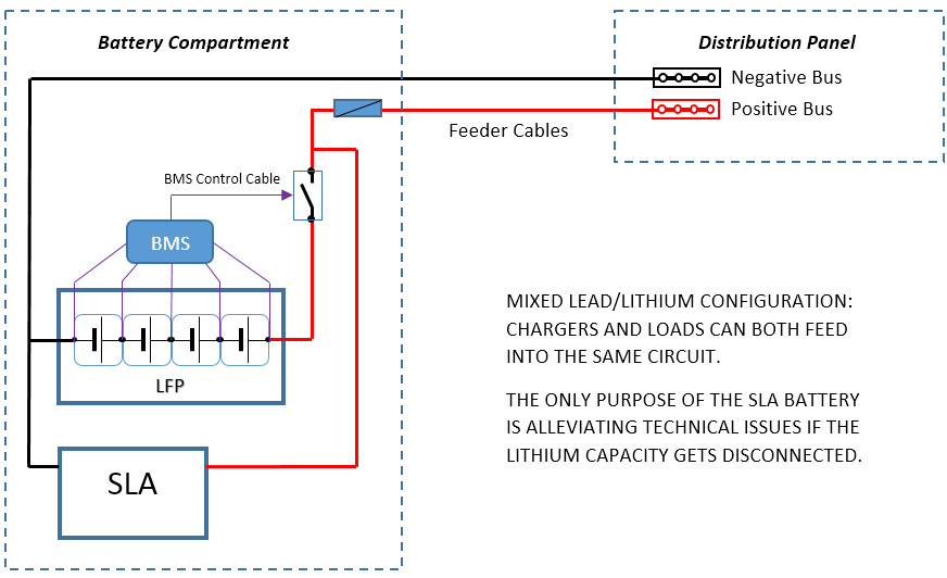
The simplest safe lithium installation: leaving a sealed lead-acid battery in parallel with the lithium bank at all times allows disconnecting the lithium capacity in case of problem without any issues. The additional SLA doesn’t contribute to any meaningful capacity; its function is ensuring charging sources always see a battery in circuit.
The practical result of such an arrangement is that the lithium battery ends up doing virtually all the work, because it is first to discharge due to its higher operating voltage. The charging voltages are no longer high enough to provide effective charging for the lead-acid cells, but as those are being trickle-charged above 13V all the time, they can be expected to remain essentially full and it hardly matters.
The lead-acid battery needs to be able to absorb whatever “unwanted” current may come its way if the lithium bank gets disconnected due to a high voltage event for example. In some instances, a single sealed lead-acid (SLA) battery can be sufficient. SLAs are the best choice for this application as they don’t consume water and are very inexpensive; gel cells should be avoided as they are costly and a lot more intolerant to overcharging and AGMs would be a complete waste of money in this role.
The drawbacks are:
- Some charge gets lost trickling continuously into the SLA, more so in a lead-acid battery in poor condition.
- It doesn’t fully eliminate the lead and associated weight.
- Removal of the SLA from the system, at some point in the future, would create an unexpected liability.
Some advantages are to be found as well:
- Disconnection of the lithium bank can be managed with a single contactor; there is no need to implement a split bus. This can allow using some small BMS solutions incapable of managing a dual DC bus.
- The lithium bank is literally added to the installation in place, normally without cabling alterations required, but not without voltage and regulation adjustments.
With this in mind, it certainly is the simplest fully functional design one can build, as long as protection and automatic disconnection are still very properly implemented for the lithium bank.
Should the lithium bank ever become heavily discharged, the additional lead-acid capacity can start contributing, but this would also leave it at a reduced state of charge for a time afterwards and cause it to start sulphating. This is not automatically much of a concern, because it may not happen (this depends on the BMS low-voltage disconnect threshold) and it doesn’t actually result in much harm if it does. The SLA needs to remain in a reasonable condition however, in order to be able to absorb any transients if the lithium bank gets dropped off due to excessive voltage and not continuously discharge the lithium cells at an excessive rate.
Voltage Sensing
NEVER, EVER, SENSE THE CHARGING VOLTAGE DIRECTLY AT THE LITHIUM BANK TERMINALS IN THIS CONFIGURATION
The sensing voltage required for charge control must be sourced upstream of the lithium battery disconnector, or in other words from the SLA battery, so it remains valid even after a disconnection of the lithium capacity. This is very important, otherwise uncontrolled, unlimited charging of the lead-acid battery will occur after the lithium capacity gets isolated.
Alternative 2 – Split Charging
Considering that, in most instances, good system design practices lead to keeping a separate SLA battery for starting the engine, one can be tempted to derive similar benefits from it, instead of carrying one or more additional SLAs as required by the Lead-Lithium Hybrid topology.
Charge isolators are extremely useful devices for building lithium battery systems and can be found in a variety of configurations, 1 or 2 inputs connected to 2 or 3 outputs. They are extremely rugged and robust. The best ones all seem to be manufactured in the USA: Sure Power Industries, Hehr and Cole Hersee are all excellent sources for quality units. Inferior products generate considerably more heat.
If efficiency is a key concern, isolators using MOSFET transistors instead of diodes are available, albeit at significantly higher cost.
Using a charge isolator (also known as blocking or splitting diodes) can provide at least a partial solution, depending on the nature of the charging devices present. It is a good option with alternators and any chargers that don’t need a voltage originating from the battery to begin operating.
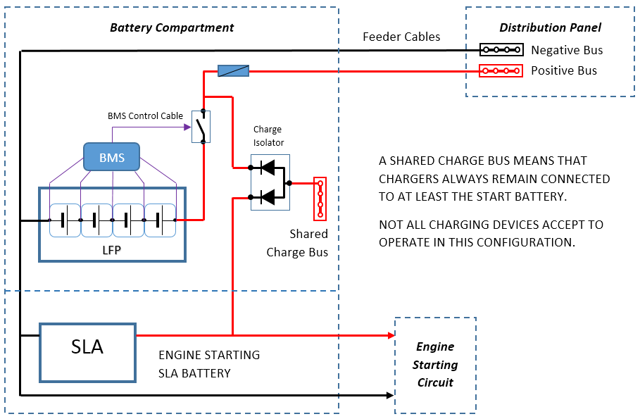
Since most of the electrical issues with the integration of lithium batteries in traditional marine systems arise with battery disconnection, splitting and sharing a common charge bus with the engine starting SLA battery is a very simple and effective way of addressing the matter.
Unfortunately, some battery charging devices refuse to operate behind an isolator; this prevents adopting this configuration as a universal solution, but it is nevertheless valuable.
Alternators and unregulated/crudely-regulated wind/tow generators are usually happy to function this way behind a diode. Internally-regulated generators commonly refuse to start unless they can “see” the battery voltage, because they require a small amount of power to first “release the brake”.
If this configuration can be achieved, then again the lithium bank can simply be dropped using a single disconnector without any ceremony, should some adverse event occur. One side-benefit is that the charging systems feed both into the lithium bank and the start battery, even though the voltage isn’t ideally quite high enough for the latter. This can be remediated by the addition of a small dedicated charger for the lead-acid battery, either solar or through step-up DC/DC conversion from the lithium bank.
Note that the charge bus still feeds into the positive bus after the lithium bank has been disconnected. The voltage from the charge bus is limited by regulation and the presence of the lead-acid battery, but the power quality may not be adequate with possible brown-outs. Also disconnecting the feeder line to the distribution panel in a battery protection event is one way of remediating this.
In such a configuration, it is very important that the lead-acid battery always remains present in the charging path. A battery switch to isolate the engine circuit is fine and desirable, but the charge isolator(s) should remain directly connected to that battery at all times to provide a pathway to dissipate any surge, as well as a nominal base load for the charge regulators.
Voltage Sensing with Charge Isolators
Any serious charge controller comes with a battery voltage sensing input. When the charger output is split to charge multiple banks, this becomes even more important as any losses over the charge isolator must be compensated for and a quandary always arises as to where to source the charging reference voltage.
Accurate battery voltage control is only going to be achieved for the battery being sensed, because there are voltage losses proportional to the current in charging systems. With a lithium bank in the system, sensing should reflect the voltage of the lithium bank and this will result in best performance for charging it; this is usually the desired outcome.
NEVER, EVER, SENSE THE CHARGING VOLTAGE DIRECTLY AT THE LITHIUM BANK TERMINALS IN THIS CONFIGURATION
Voltage sensing for a lithium battery in a split-charging topology must be performed at the output of the charge isolator, upstream of the battery disconnector, so disconnection of the battery doesn’t dissociate the sensed voltage from the charging voltage altogether: this would otherwise lead to uncontrolled, unlimited overcharging of the remaining lead-acid batteries in the system.
Voltage sensing can sometimes be performed at the input terminal of the charging isolator instead, for some equipment such as alternators typically. In this case, the charging voltage adjustment must be made for the lowest voltage drop that can be experienced over the isolator. This is normally about 0.3-0.4V for Schottky diode type units and essentially zero if a MOSFET-based isolator is used instead.
The difference in system performance is subtle and yields a less aggressive charging characteristics with lithium cells in particular.
General Electrical Installation
Fusing & Feeder Cables
A heavy-duty fuse should normally be found very close to the bank to protect the feeder cables. This fuse should be sized so it will never blow unless an intense short-circuit occurs, or it may create the potential for at least accidentally destroying the alternator, and often much more.

ANL fuses are cost-effective, easy to source and can offer interrupt ratings up to 6kA at 32V, but some are only good for 2kA.
The nominal current capacity of a fuse reflects the current it can conduct indefinitely without blowing. Currents above this value will cause the fuse to heat and eventually blow; the time it takes for this to happen is related to the ratio of the over-current and can range from minutes or more to milliseconds.
The interrupt rating of a fuse is considerably higher than its current capacity and defines how much current the fuse can successfully interrupt by blowing; values beyond this figure may result in continued arcing over the fuse after it has blown. The interrupt rating is very voltage dependent, for obvious reasons, and increases significantly at lower voltages.
Unless the feeder cable leaving the battery compartment is of an exceptional size and the battery bank is very large, a common low-voltage ANL fuse with an interrupt rating of 6kA at 32VDC is normally adequate. There is too much resistance in the cells, connections and cables to sustain the hypothetical currents (and associated apocalyptic predictions) that would supposedly arise from a short-circuit.
For a 13.3-volt source to supply in excess of 6000A, the total circuit resistance would need to be below 2.2 milliohms. Small lithium battery systems of interest for pleasure crafts normally fall short of such capability simply due to the size of the cabling used and number of bolted connections involved.
In the case of larger installations, a proper prospective fault current calculation should be carried out and the fusing should be selected to match the required interrupt rating.

Class T fuses offer much higher interrupt ratings (20kA) than the common ANL fuses and can become necessary to protect the feeder cables in large lithium battery bank installations.
The feeder cables should be sized according to the maximum acceptable voltage drop they can induce under normal operation. Quite often, alternator charging currents and inverter loads represent the maximums the installation can be expected to see.
Using unreasonably heavy cables or seeking negligible voltage drops at peak current also increases the maximum prospective short-circuit current the installation can produce and results in a higher level of risk. The cables need to be able to hold until the fuse blows and, until then, their resistance is precisely a good part of what limits the fault current: it pays to keep this in mind and take advantage of it.
Common Negative
In the case of a system with more than one battery bank – a very common configuration due to the presence of at least a starting battery – it is usually wise and sensible to tie all the negatives together, because it simplifies the integration of any device connected to more than one bank.
If charge splitting is to be used one way or another, then a common negative to these battery banks is mandatory.
Battery Sensing
Battery Voltage
If not already present, a dedicated battery voltage sensing cable with its own small fuse at the battery end should be run from the source of the sensing voltage, which often is not at the battery itself, to wherever the charging equipment is/will be located. All voltage sensing can then be consolidated onto a dedicated terminal block rather than having multiple wires all running back to the same location for an identical purpose.
A great deal of damage and destruction can result from sourcing the charging reference voltage inadequately in an installation with a lithium bank
Where the voltage sensing cable should be connected in the system depends on the topology of the installation and the subject was discussed on case-by-case basis earlier.
Battery Current
Many systems also include a current measurement shunt associated with a random number generator battery monitor or amp meter. The shunt is almost always found on the negative side, because it is technologically simpler and cheaper to measure the current there. Run a twisted pair cable from the shunt block directly to the measuring instrument.
Other than for the negative voltage sensing core and any BMS wiring, there should be nothing else than the lithium bank connected to the battery side of the shunt. This includes the negative of other batteries, such as a starting battery: failure to observe this will result in the current of the other batteries to also be measured, when it shouldn’t.
Temperature Sensors
Any battery temperature sensors associated with charge controllers and pre-existing lead-acid cells must be disconnected from all charge controllers and removed altogether. Some controllers may signal a fault as a result, but normally keep operating assuming a default constant battery temperature: this is exactly what we want. Occasionally, an ill-tempered controller may refuse to operate without its temperature sensor. Most temperature sensors are 2-wire negative temperature coefficient (NTC) thermistors (resistors whose value is temperature-dependent). Measure it at ambient temperature with a multimeter and replace it with an approximately equivalent fixed resistor (the nearest standard value will do) at the controller terminals.
This aspect is in fact part of the integration of lithium batteries with other equipment, but as the task of removing the sensors takes place within the battery compartment, it seemed logical to include it here.
Temperature sensors have their place in a lithium battery bank, but they are part of the battery protection circuitry and completely unrelated to the charging voltage. Lithium batteries in marine installations should always operate within a degree or two from ambient temperature, without exhibiting meaningful differences between cells.
Battery Switches
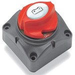
Simple heavy-current battery switches are a much better choice than combining switches with lithium batteries, as paralleling of batteries is usually most undesirable.
On dual DC bus systems, it is highly unadvisable to leave or install a battery master switch in the feed line between the batteries and the bus disconnectors. The correct way of achieving battery isolation is by opening both the charge and load bus disconnectors, which is a function that is normally provided by the BMS; failing to observe this point would again result in removing the battery while leaving both buses linked together as described earlier.
The only acceptable function for a manual battery isolator switch is turning the power off to the vessel, i.e. disconnecting the load bus.
If complete manual battery disconnection is desired, then either two single-pole battery switches or a 2-pole switch must be used to isolate both positive buses. Some analysis must be carried out to determine whether leaving the charging sources tied together at the “floating” charge bus with nothing to charge could result in equipment damage or not.
While the BMS may be able to provide “advanced notice” of a charge disconnect and turn the chargers off, a manual disconnect typically won’t.
Paralleling Switches
Paralleling batteries is a concept that evolved from trying to crank diesel engines with proverbially flat lead-acid batteries. One good engine starting battery is all it takes to do the job. Unless the engine is truly large, a single battery is normally ample, and more is just dead-weight.
If either the lithium or the lead-acid battery is heavily discharged, closing a parallel switch can initially result in an intense discharge current, with a risk going towards the cabling and the lead-acid battery due to the formation of explosive gases.
Systems including isolated banks of each type normally also include provisions for charging the lead-acid capacity properly (i.e. at higher voltages, using a temperature-compensated voltage and float-charging) and this makes the paralleling switch a very dubious proposition, because it exposes the lithium cells to a completely inadequate charging system. The fact that you “won’t leave the paralleling switch on” only means that it will happen anyway, sooner or later, because it can.
On a dual DC bus system, there is also the question of where to connect the switch: the tie-in can typically both consume and supply energy and it can only be cabled to either the charge or the load bus, leaving the system vulnerable to discharge through the charge bus, or overcharge through the load bus afterwards.
I personally prefer having the option of using jumper cables if ever warranted, rather than creating an unnecessary and permanent liability by having a paralleling switch in a dual DC bus installation.
Simple systems that don’t feature a dual DC bus can actually be designed with a paralleling switch, but it must join past the lithium bank disconnector relay, not on the battery side. This ensures that the BMS can break the parallel link if trouble is coming from there. Regardless, it is still a bad idea.
Voltage-Sensitive Relays (VSR)
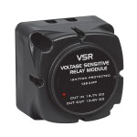
Voltage Sensitive Relays (or VSRs) are always poor solutions in marine electrical systems and, at best, next to useless with lithium batteries. The one depicted above, with a cut-in voltage of 13.7V and a cut-out threshold of 12.8V, would essentially remain closed until deep discharge has occurred.
Voltage-sensitive relays are another plague of modern marine electrical systems. They gained ground after people experienced issues with diode-based charge isolators due to the voltage drop they induce and because VSRs are seemingly easier to deal with and understand.
Each battery bank has it own state of charge and needs in terms of charging profile. Paralleling banks together is never a great idea, even when the batteries are of the same type and require the same voltages.
Some VSRs sense the voltage on one side only, others on both; some offer adjustable thresholds and others not. Unless the unit is fully adjustable and includes both low and high voltage disconnection points, it is normally completely useless (and equally harmful) around lithium batteries.
Forwarding a charging voltage from a lithium bank to a lead-acid battery won’t result in a good charge characteristics. Doing the opposite requires observing both a connection and a disconnection voltage threshold, because lead-acid battery charging reaches excessive voltages. The resulting charge characteristics for the lithium battery is typically not good either, because no absorption time can be provided. It keeps getting worse: should one of the banks become heavily discharged, closing of the VSR can easily result in a sustained discharge current way beyond its current capacity, leading to some catastrophic failure.
On dual DC bus systems, VSRs normally bring all the same issues as paralleling switches: there is no correct place to wire them in and they have no place there.
Regardless of brand or type, VSRs never seem to lead to any good solutions in systems with both lithium and lead-acid cells. Fortunately, there seems to be an endless queue of ill-inspired people keen to buy them and this makes them very easy to get rid of.
The best answer to charging auxiliary engine starting SLA batteries is using a battery isolator, if an alternator is present, and DC/DC chargers from the lithium bank (or an auxiliary solar panel) to ensure full charge can be reached. The installation can then simply be configured to charge the lithium bank optimally.
Engine Starting Batteries
Internal combustion engines can be cranked with LiFePO4 batteries, very successfully at that, and even when the battery is low on charge, within reason: a lithium bank down to 3.0V/cell can struggle to crank a diesel. There are however a number of good reasons for not doing it when the vessel is large enough to sustain a dual bank installation:
- Redundancy and the ability to still start the motor with a discharged house bank are lost.
- Unless the lithium bank is huge and a current of some 100A means little, engine cranking still causes the voltage to sag at the battery and creates transients in the system.
- Lithium batteries are harder on engine glow plugs, because they supply a higher voltage under load.
Unless low weight is everything, using a lithium battery as a separate starting battery is possible, but usually not sensible:
- A SLA purely used as a starting battery is very easy to keep at full charge and commonly lasts 8 years or more on a marine vessel. A very small solar panel can be dedicated to floating that battery at the appropriate voltage if needed.
- The comparatively very high cost (and added complexity) of a lithium battery in this application cannot be justified.
- A lithium starting battery should be kept at about 50% SOC in order to age well; it introduces a new lithium charge control regime in the system.
- As highlighted earlier, there are often technical benefits to be found in still having a SLA in the system and dedicating one to cranking the engine is a good use for it.
Next Steps
Once the new battery bank has been balanced, assembled, protected and installed in an electrically correct configuration as described above, it needs to be integrated with existing charging equipment.
Due to the large variety of gear found on the market, with hardly any of it ever intended or properly designed to charge lithium batteries, chargers require a lot of attention in order to function without tripping the high voltage protection limit or overcharging the bank over time.
The subject is extensive enough to be treated separately.
This is a really good article. Thanks for the time you took to write it and I hope it helps a lot of cruisers!
Bob,
Thank you for your kind words, you have been in this field for quite a while… Late last year I saw a lithium battery fiasco of such a magnitude that it prompted me to start writing this material. At the time, the owner didn’t even understand how and why it had suddenly gone so wrong.
The electrical engineering component present in these systems is too often not identified properly or discounted, but it really is the backbone of the installation.
Best regards,
Eric
I built a device (micrcontroller/relay) that desconnects the generator field when 14 V has been reached.
The field is reconnected at 13.35 Volts.
I was thinking to reuse my lead-acid battery charger by controlling it through the temperature sensor input.
Instead of an NTC I would just use o fixed resistor that lowers the end of charge / float voltage.
Or even better measure the charge voltage by a microcontroller and adjust the resistance so that a float voltage of 13.3
Volts would result. The idea is just to prevent any further charging when 14 V battery voltage has been reached.
Have you or anyone tried this kind of approach ?
Hello Mike,
Good on you for engineering something. Lithium batteries need absorption like any other battery and disconnecting at 14.0V will produce very unsatisfactory results unless the charge current is very small. Charging will stop a long way short of the nominal capacity and serious problems will develop over time due to systematic lack of proper charging. The only fully correct charge termination condition is based on voltage and residual current, typically C/30.
You can certainly fool and control a charger to do something else than it was initially intended for. Using the temperature input is a thought as long as it doesn’t decide that the value has gone out of range. You need to test that with a potentiometer – which you might have done already. The other way is manipulating the signal at the voltage reference input. We have done that with alternators for a few years now. When the charger/regulator has multiple stages, the solution must be able to work with them. It is easiest and simplest when the charger provides a constant voltage.
Now, this is charge control. The bank still needs to be protected independently of that of course.
Best regards,
Eric
PS: I have an article about charging lithium batteries at draft stage. When I publish it, I might move your post there.
Thanks Eric.
Your articles on LiFePo4 are the best on the internet.
My primary concern is to not overcharge. I am not that concerned with getting the full charge, I just want to stay on the safe side. My Hitachi alternator gives out just 5 Amps(C/20) at 14 Volts, that is an approximate current based end of charge together with the 14 Volt limit. I can configure the voltage to a bit higher to get a lower current termination point.
My (other) PIC18 based controller also measures the current, so I could include the current in the algorithm.
Eventually the controller should control the charge current from solar, alternator, and charger.
And it should measure the cell voltages also.
My battery charger actually has a constant voltage output setting of 13.2 Volts for continuous Pb battery load carrying.
I will check how the temperature sensor input does control the output voltage with the above setting.
BR Mike
Mike,
Getting a proper charge, at least from time to time, is extremely important too with LiFePO4 cells, otherwise the voltage starts rising earlier and earlier over time and the available capacity starts shrinking. There is a memory effect taking place over time with partial cycles and incomplete recharge.
When you charge with low-power sources, the battery has more time to absorb the charge and the voltage doesn’t rise as quickly, so it mitigates the problem. Increasing the voltage above 14.0V makes the pack a lot less tolerant to small differences in cell balance and more difficult to charge unless you have good cell balancing circuitry. Cells always seem to drift apart a little over time.
I have seen cells completely destroyed even though the pack voltage had never gone over 14.0V due to severe cell balance issues. Once a cell starts getting stressed during charging, it gets damaged and everything falls apart. You can live without automatic cell rebalancing and make manual adjustments from time to time (after 2-4 years in my experience), but cell-level monitoring is the foundation of everything with lithium.
You should be able to find the output voltage feedback in the regulation circuit of your 13.2V PSU and alter that if needed.
Best regards,
Eric
Dear Eric,
It will be interesting to see how the cell balance will drift. My plan is to use a C/20 top balancing charger from time to time, maybe once per year. It is one of those made for the R/C market.
I also have a balancing board that could be connected permanently, but I want to see first how the cells behave. It will balance at any charge level, and that is maybe not a good idea.
I managed to get the WAECO MCA 1225 charger to charge to 14.0 Volts and float at 13.4 by connecting a 47.5 KOhm resistor as temperature compensation. The charging turns to floating at 14 V / 1.5 A(15 minutes) charging current. Then I just manually depower the charger, I will not keep it floating for a longer time.
Looks promising.
Maybe I should lower the float value to 13.30 in order to get some discharge from the battery. Not to keep it full all the time. This would drop the charge voltage a bit, to maybe 13.9, but with the current based EOC, it should not be a problem. 13.3 Volts would allow the charger to bear the load from the fridge and other in harbour equipment, while not further charging the battery.
Using the CV mode would require some support circuitry to stop floating the voltage at the higher level. I’ll skip that for the time being. The “temperature compensation” method looks good to me.
Best Regards,
Mike
Mike,
Cell balance adjustments in a top-balanced pack can only be performed when the cells are very close to full of course, and this means when the voltage is rising in the upper knee of the charge curve. The current must also be low so the voltage really reflects the state of charge, not the internal resistance of the cells. Attempting to rebalance the cells blindly each time the voltage is above a given value doesn’t work, unless the charger is very small.
Floating has no value at all in terms of charging, absorption is what matters, and then charging needs to stop. Configuring a “floating” voltage that is lower than the resting voltage of the cells is one way of causing the charge to terminate and then it can contribute to powering the loads and prevent the battery from discharging too far again as you say.
Best regards,
Eric
Dear Eric,
Just to continue on my previous message.
One problem with the EOC current is that if the fridge compressor starts every 10 minutes, and the charger expects the EOC condition to remain for 15 minutes, the EOC charge condition may never be reached.
So I guess that to really define the EOC condition, the current of the consumers should also be in the equation.
Best Regards,
Mike
Mike,
This issue primarily arises when the charger tries to determine the EOC condition by measuring its own output, which is only correct in the case of stand-alone charging. If you are charging into a system that is also powering loads, then it is the battery current, not the charger output current, that matters. A charger suitable for a system of the type we are interested in must use an external current shunt to measure the battery current only.
Obtaining a complete picture of the current flows (sources, loads and charging) requires two shunts and then the third value can be calculated of course.
When the fridge compressor runs, the charger should try to maintain voltage regulation at the absorption setpoint and the battery current shouldn’t change. The EOC condition only needs to last long enough to avoid false positives, like when throttling down an engine while the battery is in absorption. This is a matter of seconds, not minutes. The battery current value usually needs to be filtered too, so brief fluctuations don’t cause an early termination.
Best regards,
Eric
Eric,
First, I have enjoyed reading all your write ups on your experiences with LFP battery configurations.
Some background. I have been cruising for 22 years. Getting old so transitioning to a 44’ power catamaran. I experimented with drop-in LFPs in my last boat and was quite impressed. I am knowledgeable about wiring and rewired much of my last boat over the 15 years I owned her.
After 6 months of reading everything I could get my hands on concerning installing LFPs and the issues with charging sources, high voltage and low voltage disconnects, etc., I came to the conclusion that the system needed some way to deal with the lack of a battery should a HVD or LVD event occur. Looking at the charge profile of the various lead-acid batteries, it seemed to me that a SLA-FLP combination might work. Looking around the internet I found 2 discussions of this approach and one of them is your article here. Apparently, you agree that such a hybrid system could deal with the, hopefully, rare LVD event. In addition, it seems that you agree that it could also handle a less rare HVD event where solar, charger, or alternator try to overcharge the FLP pack.
Are you aware of anyone actually implementing this approach? How has it worked out for them? It seems to me that a second (failsafe) HVD (and LVD?) would be appropriate in this design to guard against a failure of the primary battery protection device.
The new boat is wired for four battery banks. 1 each for the engine start batteries. 1 for the generator start battery. And 1 for the house battery. Catamarans are of course weight sensitive and this is crazy. I intend to get this down to 2 banks as I did with my previous sailing cat. One starting battery for the stbd engine and generator. One bank, a hybrid 800 AH FLP/200AH SLA, for starting the port side engine as well as for the house bank. With emergency crossovers of course.
My expectation is that by keeping the SLA in parallel with the FLP bank I will not have to redesign the alternators or their control circuits. In addition, though I intend to modify the inverter/charger profile and the solar charger profile to FLP compatible values, I will not have to be concerned should something fail and try to over charge or over discharge the FLP bank.
I would be very interested in your feedback. Although there is much written about LFP batteries, most is EV, or RV related. There is not much marine related experience, and this definitely seems to be a marine only solution.. The other discussion about an approach such as this seems to be a dead thread.
Apparently your BMS is not ready for production. I am currently considering the Orion Jr. Do you have recommendations?
Thanks
Bryan
Bryan,
Lithium batteries will deliver the same performance regardless of how they have been packaged in these applications. The difference will be in durability. The disappearance of the battery from the system is the key critical issue with drop-ins of course, because they disconnect without any advanced warning. The only practical way of dealing with this is creating a hybrid bank indeed, with some “permanent” lead-acid capacity.
However, the capacity of the lead-acid isn’t truly additive, because once you configure the installation to charge the lithium cells sensibly, you also lack the voltage to properly recharge the lead-acid cells if they have been cycled. As a full lead-acid stands at 12.8V and a lithium bank at the same voltage is around 13% SOC, it is quite straightforward to see that the lithium is going to be doing all the work up to that point (which is nearly all the time).
The fact that the battery is packaged (usually with a lot of marketing first and foremost) only gives you protection against a battery fire and nothing else. It doesn’t change the facts that:
– The cells will get damaged if they go into over-voltage territory.
– The cells will also get damaged if they are getting chronically over-charged (which can’t be controlled with voltage). You still need to provide charge termination.
– The cells can and will go out of balance and unbalanced cells will go over-voltage at the end of every charge cycle.
– The only avenue you have to rebalance is going over-voltage periodically and if the imbalance becomes severe enough, it will cause a disconnect.
– If you happen to connect two packs in series to make 24V, then the packs have no way of balancing unless you drive a whole battery over-voltage.
Creating a hybrid bank only solves the disconnect problem. You still have to limit the maximum charging voltage to 14.0V, get rid of temperature compensation and provide charge termination when full / prevent recharging into a full battery. This last point is always the most challenging as lead-acid charge controllers are designed to keep a battery full and trickle charge it if needed. It is the case with any kind of lithium system, but a decent BMS can help you with this. With packaged lithium cells, you are usually flying blind.
I know of one installation that has been operating for a few years with some lead-acid capacity in parallel with packaged LFP cells and an adjusted charging voltage, but the owner cycles it daily and supervises charging manually. It turns into a headache with no really acceptable solution when he wants to leave the boat for a while without turning everything off.
Emergency cross-overs with lithium create a hazard as they basically connect a lithium battery to a charging system that is not suitable for it and the cross-over can be left on inadvertently. People swear that they won’t allow that to happen, but it makes no difference from the angle of liability, insurability etc. It is not something to have around. Use a jumper cable if you ever have to.
An inverter/charger can work for you, but only because you won’t be able to create a dual DC bus system.
A proper lithium-ion BMS is not an option for you if you start with packaged batteries, because you don’t have access to the cell voltages and your capacity is fragmented across a group of “12V strings”, instead of “3.3V blocks”. A BMS is all about individual cell voltages and current. When you buy a “drop-in” packaged battery, you typically buy a bunch of small cylindrical cells (because they are cheaper than prismatics) and a low-cost “disposable” BMS with every single battery. It makes little technical or economical sense to try and assemble a large capacity bank this way. If you are thinking about a BMS, then you should be buying bare cells and build your own bank.
My time got diverted by other work for quite a while, but I have been back on the new BMS project for the last few weeks with a view of finally bringing it over the line. The next iteration of the hardware will hopefully be the final one and only a little more effort is needed on the software.
Best regards,
Eric
Eric,
Thanks for the response, although I apparently was not clear enough. I will try to correct that here.
While I have tried drop-in LFP in the past, my current project is intended to use individual cells in a 800Ah pack with a BMS to control LVD and HVD events. On my previous boat I only had 2 battery banks (after my modifications), one small starting battery shared by 2 main engines and the generator and the house bank which for the last year was 2 SMART LFP drop-in batteries in 300Ah size. I only had 3 months of true cruising experience with the drop-ins, and even though I changed nothing on my solar, shore power or alternator charging systems I did not experience any power loss from disconnect situations. If these batteries were disconnecting due to high voltage during charging, it never became apparent. In that installation I only had a very small starting battery as my second bank isolated from the house bank by an ACR. Thus it is clear that I never saw a LVD event and if a HVD ever occurred it was masked by the small starter battery and the HVD re-connected after the charging current died before the small starter battery was impacted.
My goal was to avoid a major re-wire of the new boat upon arrival while still getting the benefit of a LFP house bank. That combined with the inherent issues of dealing with two engine alternators, and a new Victron Multi 3000 on an all 12V boat led me to look at alternatives that would still allow me to install a reasonably sized LFP house bank. The solar installation will be done after boat arrival as well as the LFP bank. The boat comes stock with 3 200 AH starting batteries and 4 200 AH house batteries. The house bank is too small and the boat has way more starting capability than it needs. So, I was intending to delete the generator starting battery by sharing the starboard engine starting battery. In addition, I would delete all the house batteries and use the Port starting battery as a “front end” to the new FLP house bank and wire it as both house and port starting battery. Thus the emergency start cross over capability should either bank be dead. In 15 years with the last catamaran, I never had to use the emergency start crossover so I don’t worry much about accidentally leaving it on.
I agree with your assessment that the SLA is not “additive” to the house bank in the normal sense. In this case, the battery needed to exist anyway to serve as the starting battery for the port engine so nothing is lost if it does double duty as the “bottom end” of the house bank. However, it seems to be just the ticket to allow for the fact that current generation charging sources are not smart enough to deal with the FLP batteries. If controlled by a BMS that can actually determine SOC based on Voltage and charge rate vs capacity, an HVD could disconnect the FLP bank and allow the SLA to deal with the fact that the various charge sources are designed for lead-acid characteristics. This would also allow the SLA battery to get the charge it needs to stay healthy by staying connected during the HVD and absorbing the normal SLA charge cycle. Even with a BMS that is voltage driven only, a little hysteresis, say dis-connect at 14.0 to 14.2 and connect at 13.2 to 13.4, should keep the system from cycling too much while still protecting the FLP bank.
When the FLP bank disconnects from LV, one would hope that the SLA battery still has enough capacity to start the engine. This would certainly dictate a reasonable LVD voltage set point. In addition, the loads that depleted the house bank need to be disconnected so as to not continue to deplete the starting battery (LVD disables the inverter output and most house loads). However, if this battery can stay connected to the solar controller, the LFP BMS and the engine system as well as the inverter/charger (with the inverter hopefully disabled), then charging can resume at any time there is a source and the BMS can re-connect the LFP accordingly.
I am currently proceeding on the assumption that this type of system would work. If the parallel system you are aware of is working as a manual system, then this should be able to work as an automated version of that. One of my concerns is that the BMS becomes critical to the health of the system. I am currently looking for a way to provide a fail safe, e.g. a voltage sensitive relay, for the high voltage side which I believe will be the more “active” case.
All of the above clarifies my interest in your proposed BMS and the other option I mentioned, the Orion JR. I believe this approach can “fix” all of the problems of disconnecting and re-connecting the LFP battery bank without the expense and labor of re-wiring the boat, adding external alternator controllers and dual alternator controllers, special solar controllers, separate chargers and inverters, etc. While the system may get modified over time, it makes more sense to me than replacing a lot of brand new equipment.
Bryan
Bryan,
Yes, I didn’t realise that – this time – you were not intending to use drop-ins again. The reason why they “worked” last time without changing anything else is because they have HVD levels set ridiculously high precisely to prevent them from disconnecting when installed in a lead-acid system. This allows the cells to get ruined over a period of time in order to secure the sales and, in most cases, by the time the battery is destroyed, it will hopefully also be out of warranty.
The situation with bare cells and a BMS is not much different in terms of impact on the existing installation however.
First of all, the battery disconnection scheme is a safety system that should never operate, not a way of controlling charging. Relying on HVD to terminate the charge of the lithium would be both bad design and poor in terms of performance, because the lithium would get no absorption time and this can represent around 30 minutes when charging with a lot of current, like what you get when running two engines and alternators in parallel. The consequence of this is that you still have to control your voltage properly, from all sources. This can require changes and investment.
If you use a proper lithium BMS and don’t built a dual DC bus installation, then a HVD means loss of power everywhere and the system can’t recover from a LVD, because it also loses the ability to recharge. This is due to the single disconnect point. This is generally undesirable on a boat. Leaving a lead-acid battery in the system at all times resolves the disconnect issue as discussed in this article and also leaves you with some power after a disconnect, so it mitigates the problem to some extent.
If you build a dual DC bus system instead, then you must separate the loads from the charging sources. This means some rewiring, but not rewiring “the whole boat”. In a dual DC bus system, you can also keep a lead-acid battery hanging off the charge bus to alleviate the HVD event. Or you can use a starting bank on the other side of an isolator as I describe, at least with some of the charging sources. This is where an electrical engineering component creeps in.
However, once you build a dual DC bus system, you are NOT allowed to draw current from the charge bus or charge into the load bus. This means that you have no proper place to connect a combined inverter/charger and you need to choose between the inverter or the charger and not try to fudge it.
On the same token, if you never used the cross-over switch in 15 years on your previous boat, the correct conclusion is that you don’t need it, not that building a hazard into the system is ok.
If you leave a lead-acid battery in the system after a LVD, it won’t do you any good in terms of capacity. Using a high LVD on lithium would be idiotic because you then deliberately deprive yourself of the deep-cycling ability of lithium for no gain: you would be left with a smaller lead-acid battery that will run flat before the lithium bank would really get low. LVD for a lithium house bank is typically 2.8V/cell with a warning alarm at 3.0V/cell. By then, you would have drawn your lead-acid battery down to 11.2V only and it wouldn’t be of much use to start an engine. If you want that battery for cranking, then it must be isolated like I describe so it doesn’t discharge with the lithium. A hybrid bank only resolves disconnect issues. There isn’t really anything else to be gained or obtained from it.
So the answer to your question is that there is no quick fix or shortcut with a dual DC bus system. If you don’t build a dual DC bus system, then you can simplify things at the cost of functionality/resilience by using a hybrid lithium/SLA scheme, but it is just going to behave like a single battery of course. It can’t be two banks while also being one. Even so, it still isn’t a quick fix.
The reason why the manual system has been working is because it has been managed manually AND all the charging voltages were adjusted. The owner has to manage it this way because it can’t be automated: he used drop-ins and the BMS is of no help. With a proper BMS, there are additional things you can do, but implementing charge termination means creating a way for the BMS to get the charge controllers to cut out and this is also a little engineering project. Regardless of what you do, once you are charging lithium cells you have to make all your charging voltages and charging profiles acceptable for the lithium. Battery charging requires voltage regulation, you can’t do it by pulling the plug.
Sometimes you can modify or trick the equipment in place to make it work more like what you need to achieve, and sometimes you have to replace it.
If you chronically fail to recharge LFP batteries properly, they develop major memory effects and you can end up with hardly any usable capacity after as little as 3 years.
The bottom line with lithium is always that the job needs to be done properly, or:
1) It will be intrinsically unsafe
2) Your investment won’t last
3) Performance will degrade early
A lot of DIY systems are unsafe and/or contain hidden flaws capable of causing very extensive damage. A number of commercials have sold very high-cost safe solutions into the high-end market and got burned due to premature failures. However, it is possible to build safe and long-lasting systems and this is the topic of these articles.
Eric
Hello Eric,
Thanks very much for making this information available. It is a lot of work to document a system in a clear manner so it is useful to others. Your time is much appreciated.
I’m just designig my system now and was curious about the base in the photo of the Tyco relays. Did you make that yourself? If so, what did you use?
Thanks very much,
Bruce
s/v Migration
Hello Bruce,
Thank you for writing.
I made the base board for the Tyco relays myself indeed. The material is known as Nylatron, it is very tough and a good insulator. It is sometimes used in electrical switchyards. You don’t have to use this, but be extremely wary of the connections becoming loose over time, especially if the plastic yields. I strongly recommend having nuts below as well as above the terminals, so you don’t rely on the pressure through the base board to keep the connections tight. Some people have damaged the relays from heat because the construction wasn’t quite good enough.
Best regards,
Eric
Eric,
I am currently engineering a system for my 46’ Sailing Cat for worldwide cruising. (So far my only purchase is a quality benchtop power supply) I have found that a sound investment at the beginning of a project saves a lot of money by the end. I have spent a lot of time reading your articles as well as many others but still long way to go. A few questions about this article:
I feel that a dual bus system is definitely the way to go. In your split charging schematic, you show a single disconnect between the isolator and the lithium bank. I would assume that this is for a HVD only which would allow the charge side to maintain some power to the house with the SLA essentially being the control for the chargers. I understand that this is a safety and should never actually happen if the charging is set up correctly, however, Murphy tells us that components fail at the worst possible times. Would the LVD then be prior to the load bus but still allow the charge source to recover the lithium bank? Did I miss something?
After you mentioned memory, I read a couple of research papers on it an am left with some confusion. While it appears that the accepted school of thought is that memory is not a problem, what has been your experience to alleviate this issue?
Finally, many people seem to like the Clean Power Auto BMS but they no longer sell to the DIY market. There are so many BMS options out there, I am scared of ending up with a junk BMS but I also don’t want to get something that has more features than what I really need. Paying high dollar does not always equate to high quality. And being in the middle of the South Pacific is no time to end up with no battery bank. Any advice on a good quality, simple BMS? I plan on manually balancing periodically.
Thanks in advance for any insight and for your very informative articles.
Scott,
Schematics showing a single disconnect are NOT for a dual DC bus system. Once you disconnect the lithium bank, it can no longer charge or discharge, so by extension it can’t recharge and recover from a LVD event. Whether you also lose power to the on-board loads depends on the configuration and whether there is charging current available or not. Studying the schematics answers these questions. The SLA is there to leave a load for the chargers and there are a few variations possible in this direction.
A dual DC bus system is the solution of choice for an ocean cruising boat, but it tends to require more analysis and engineering to address all issues. If you feed the charge bus from an isolator on a dual DC bus system, then you can divert the current to another battery in the event of a disconnect. Great concept, but some chargers refuse to work when wired this way, because they see no battery voltage… Every lithium system tends to be a small engineering project because of differences in the equipment involved in it. Sometimes you need to test some of these things to discover what you can and can’t do.
The system needs to be robust no matter what happens. Anything that can happen will sooner or later happen. HV disconnects do happen. All it takes is a poorly regulated charging source, like many wind generators are, a lead-acid charge controller doing something stupid or just poor voltage sensing somewhere. I have seen a bank tripping because there was a problem with a cell link connection: it was tight, and yet not good. Battery systems are often also high-current systems and they can be unforgiving.
The BMS you are referring to was a little solution designed to help people playing with EVs, which is a simple application where you either have a charger and no load, or a load and no charger. Fine. Some people started installing it on boats and it caused a remarkable amount of destruction due to the single disconnect point that left the chargers connected directly into the loads with no battery to help with voltage regulation. Most of the systems built with it are not fail-safe and/or plain unsafe. I have seen entire electrical systems fried because it had simply tripped. It should be pulled out.
While you do not always get what you pay for indeed, you don’t tend to get more than what you pay for either. I believe there a few usable BMS units out there, but nothing I am completely pleased with. So I build mine when I need one. One of these days I might manufacture a batch of interesting BMS units, but there is one unusual feature I want to include before that. A BMS should look after cell balance and should not require unusually high cell voltages to do so.
Capacity reduction from memory effect following repeated partial charges is a fact. It happens and it is visible. If you keep at it for long enough, you end up with severely reduced capacity. If the system is set up to charge properly, my experience is that the battery gradually recovers over a number of full charge cycles. If the end-of-charge voltage is insufficient, it can’t, the situation keeps getting worse and you end up with hardly any usable capacity. We are slowly coming out of winter here and my bank has seen well over a hundred partial cycles without full recharge. It charged to the termination point a few days ago and the same evening the voltage was already below 13.2V. That is memory effect: around 40% capacity unreachable because the voltage rises abnormally early in the charge cycle. It does recover as long as you don’t listen to the conservative-over-conservative charging “recommendations” forever repeated around. Lithium iron phosphate batteries need to be charged properly up to a termination point: “weak charging” is not a substitute for charge termination.
If you are in a situation where you recharge to full easily and relatively frequently with enough voltage, then memory effect is essentially non-existent. Lithium batteries need absorption just like any other battery.
Last, but not least, you need to understand what you are doing and why you are doing it when you build a lithium system. I believe you can always get there if you put enough time and effort into studying the matter. You need to perform a what-if analysis on your schematic before buying or building anything. The objective of these articles is supporting this process.
All the best,
Eric
Thank you for this series, it has been an absolute delight to absorb these articles.
It seems nearly impossible to find information this condensed and accurate on the subject. Many sources seem uninformed at best and dangerous at worst. Can’t wait for the article on charging, as it is the final pain point I’m struggling to get right, before building my own setup.
You rock.
Niko
Thanks Niko. I will try to get the article on charging out and finish the series. Finding the time to finish the draft while also progressing the BMS is a challenge…
All the best,
Eric
Hi Eric,
Many thanks for a very informative and well written series of articles on LiFePo4 installations on boats, an awful lot of information presented in a very understandable way, especially helpful is the “failure mode analysis” that covers many things that often get overlooked when designing a system. Most systems get designed around the concept of “how will it work” when they really should be designed around the concept of “how will it fail” – this tends to produce a much more robust system.
I am currently designing and planning a LiFePo4 installation on board our 42ft cat as well as a system for a 50ft cat, both systems will be installed over the coming winter and your articles have been very useful. Both systems will use Winston prismatic cells with 400AH at 12V on our boat and 400AH at 24V on the 50ft. You suggest that 200AH is enough for most boats but boats are generally more power hungry these days and both these boats are full-time liveaboards so the extra capacity is justified since the aim is to be able to run off-grid for extended time periods that requires powering fridge, freezer, large capacity watermaker and many other consumers. The larger capacity will allow for 2 or 3 days without sunshine if needed. Main charge source for both boats will be solar with alternators and mains chargers as additional sources.
The dual bus system is obviously the best solution but both boats will have Victron Inverter Chargers so this will not be possible since the Inverter Charger can be a load and/or a charge source. I do think the Victron units are very good and they offer functionality such as Power Assist that does not seem to be available on Inverter only units. In addition the Victron units allow for external signals from the BMS to turn off the inverter function and to turn off the charger function as required so it seems they can be safely integrated into the system although I note your aversion to combined Inverter Chargers.
After much research I have decided on the Orion Jnr BMS and although you shy away from making specific recommendations I note that some of the control function terminology in your articles is identical to that used by Orion so I guess you consider it be one of the better BMS units available. The Orion Jnr does give enough configurable outputs to allow designing and implementing of multi-stage protection levels and the software application is also very good.
I am sure your forthcoming article on charging systems will cover the various factors to be considered and I hope you manage to get it completed before I start installing the systems 🙂
All the charge sources will be fully configurable to provide the correct voltages and charging profiles to suit the LiFePo4 batteries – alternators will have fully programmable external regulators, solar will be controlled by Outback or Victron MPPT regulators and mains charger will be Victron with full control of charging parameters.
I am planning to configure all the charge sources with the correct voltages and charge profiles to properly look after the batteries, this is effectively the first line of defense and should provide proper battery management in almost all conditions and circumstances.
The BMS will provide further protection so that if cell voltages rise higher than the charge sources are programmed for due to any malfunctions then the BMS will turn off the charge sources – alternator regulators turned off, solar disconnected before the regulator and mains charger turned off using the Victron internal functionality. This is then the second line of defense.
Finally if cell voltages rise still further for any reason then the BMS will open the main contactor to disconnect the battery – so a third line of defense.
A similar functionality is planned for low voltage control although this will likely not be as comprehensive but will ultimately disconnect the batteries if voltage gets too low.
I am planning to include an audible alarm to operate just before the main contactor opens at both HVC and LVC, I understand your aversion to alarms for very valid reasons, however the Orion BMS has sufficient outputs to allow including the alarm just before the contactor operates so I feel that it cannot do any harm. If no one is around to respond to the alarm then the BMS will operate the contactor anyway so the batteries are fully protected.
Since the system will only have one main contactor a HVC or LVC disconnect will mean the system will not be able to recover without user intervention, indeed the Orion BMS actually requires a power off-on cycle after this event so user intervention will always be required. Given the other levels of defense designed into the system this event should never happen so requiring user intervention is an acceptable consequence.
I would be very interested to hear your thoughts on the system design outlined above.
Hello Chris,
The capacity of a system is determined by its intended regime of operation. 200Ah systems have proved to be very capable of sustaining vessels with full-time live-aboard couples running reasonable loads today like fridge, freezer and TV. The fact that people sometimes want to design for higher consumption levels doesn’t change that. What must be remembered is that all energy drawn from the battery must eventually be replenished and a larger bank often means longer recharging times. If recharging cannot be achieved using renewable sources like solar, then in my opinion the overall energy usage on board should be scrutinised in terms of efficiency and actual necessity before anything else, because running engines/gensets can hardly be called a “solution” and all proclaimed “needs” are not sensible needs.
I don’t personally see a lot of value in “inverter power assist” and I certainly wouldn’t place such a feature ahead of the functionality offered by a true dual DC bus system, but these are choices for you to make.
The issue with combined inverter/chargers is not one of functionality, but one of system design. If you are charging into the load bus and somehow you lose control of it (all it takes a broken wire or electronic failure), the BMS will disconnect the charge bus with no effect. If you breach the system design boundaries, you also compromise the intrinsic safety of the installation. You must remember that one day the equipment may not operate as designed/as you expect and then you need to have at least one last measure in place to protect the bank. The DC disconnector is the last line of defence.
I think I have provided enough information to make informed choices regarding a BMS for anyone who is prepared to download and study product manuals. I have always built my own BMS modules, never installed anything else and any commonality in terminology with one product or another would be coincidental. But by studying and analysing what is on the market in terms of capability and suitability for your design, you are following the correct pathway.
You are very correct when you write that having charging sources that do not operate in a way that represents a hazard for the cells is the first line of defence. Building an installation that does not challenge the protection system in normal operation is essential. However, chargers typically cannot determine the end-of-charge point in this type of application, so the BMS needs to provide additional functionality for battery management, like preventing systematic overcharging for example.
Implementing a staged protection scheme is indeed the way to go: try to eliminate the problem before taking a protection measure. This can be particularly important to prevent damage when charging if a disconnect is going to leave a charger with no load. Just keep in mind that having to “power to disable/protect” easily results in systems that are not fail-safe.
Alarms have their reason to be and all on-board lithium battery systems should have an alarm, at the very least to warn the owner ahead of a low-voltage disconnect. What alarms are not is a prompt for the owner to do something to prevent a dangerous situation to follow. An alarm should warn of an upcoming event or an apparent malfunction like a voltage regulation failure, but it should never mean “danger” by design.
It is for you to decide what level of resilience is acceptable indeed. As long as you do this with the understanding of the limitations and requirements it also brings, you can’t go wrong. In the worst case, you may one day have to live with the full consequences of what your design can produce, so make sure this is indeed acceptable.
I get into the specifics of equipment, compatibility and details of system design only when I consult on projects. This site is intentionally “product and brand neutral” and free of advertising.
All the best with your project,
Eric
Hi Eric,
Many thanks for your wise words, very useful.
The intention is that solar power should meet practically all the power supply requirements for both systems, indeed both vessels will likely be able to fully charge the battery bank by early afternoon in normal usage so leaving some surplus charge capacity to cover cloudy days and above average consumption. Alternators and generator are only really a backup to the solar and not part of the designed charging provision, albeit yachts do much more motoring than we like so we may as well use the alternators provided they are properly regulated.
The “power assist “ functionality has proved useful in the past hence my reasons for including the inverter charger, although consideration of future plans may mean it is of less benefit – one to consider carefully before finalising the design. Both vessels already have Victron inverter chargers and although it is not always best to design to include existing kit they are expensive units to replace so that also has some weight in the overall design decisions. Your concerns about some failure causing charging into the load bus is very important – obviously including an inverter charger unit prevents the use of the optimal dual bus system so there will only be one main contactor as the last line of defence that will operate at HVC and LVC so the system should be fully protected. The system will also be designed to make sure all charging sources are safe (as far as possible) if a battery disconnect occurs. I will try and think through all the potential “failure scenarios” and factor them into the design.
You certainly have provided plenty of information on the functionality required for a BMS and I fully understand your reluctance to make any specific recommendations, very wise – unfortunately most of us are not gifted enough to build our own and have to use the best we can find on the open market!!
Determining the “end-of-charge” point for LFP banks is a difficult problem since house bank usage inevitably means very variable charge and discharge times and currents over any period of time, very different to, say, an electric car that is either being discharged or charged (ignoring regenerative charging). At the moment I feel there will be sufficient functionality in the BMS to address at least some of the problems – since I will be living with one system I will be able to properly monitor and modify as required to try and ensure proper charging and prevent regular overcharging. Indeed it would seem best not to strive to get the last 5% of capacity back into the bank on a routine basis at the risk of overcharge. Obviously the ability to adapt the system at will is not a suitable design for remote systems although the other boat will likely be close by for a good length of time. Almost everyone is still learning about LFP banks on boats so it is almost impossible to say “charge to this voltage, this current and this length of time” it will always need to be an adaptive target – a consideration that must be included in the design. I would think even a fully monitored CAN BUS type system with variable current, voltage and time control of all charge sources will not be guaranteed to properly charge the bank, but it will obviously be much better than simple voltage control used by most charge sources at present. Unfortunately designing such a CAN BUS system is far from a trivial task and the market for such a system for house bank applications is probably still pretty small.
Your comments on alarms are pretty much the same as I had planned, they can only ever be a warning, since there will always be a time when no-one is around to hear the alarm and act on it. Final protection of the battery bank must be fully under the automatic control of the BMS. As you rightly say “power to disable” has no place in a properly designed fail-safe system, the only part of my system design requiring a “power signal” is the alarm itself, all other charge and discharge functions will be “power to operate, no power to disable”
Thanks again for your valuable input and time taken to reply.
Chris,
A lithium battery is charged when the voltage has reached a nominal value and the current has decayed below a threshold. Determining the end of charge is not more difficult than this and any decent BMS can help you with doing it. A system where the charging sources are under the control of the BMS can definitely charge a lithium battery correctly and this is should be the aim in any installation.
Voltage doesn’t “control” the charging of lithium batteries at all, as I developed in another article. Any voltage above about 3.4V/cell can fully charge and overcharge a lithium battery and – in my experience so far – any voltage below 3.5V/cell can also fail to recharge a lithium battery properly if it has done a lot of partial cycles and it is showing a memory effect. If the latter happens, battery health will start heading downhill.
Charge correctly and wisely and the battery will have a very long healthy life.
You can certainly design with a single common DC bus if the drawbacks are acceptable to you. Otherwise use the inverter/charger as an inverter only. I find mains chargers to be of very limited use in practice. If you have reasonable solar capacity and shore power available, run your some of your primary loads like refrigeration directly off the mains if you have to and everything else normally takes care of itself. Unlike most other power sources, mains chargers have the potential for relentlessly overcharging a battery and potentially drive it into thermal runaway and the safety engineering around them better be really, really good!
The #1 rule with industrial safety is “eliminate the hazard if possible”. Here, it is usually possible, so I always prefer when people don’t set themselves up for an accident by trying to mimic a lead-acid setup.
Best regards,
Eric
Hi Eric,
Perhaps I am trying to make things more complicated than they really are – I am very happy to hear your advice that voltage level and current threshold should be enough to ensure proper charging and minimise any risk of overcharging. Certainly the planned BMS has current monitoring and control that will be utilised so it seems I am overthinking things at this stage.
Mains charging is not an important factor in my plans since both vessels will be mainly off-grid and treating the inverter chargers as inverters only is certainly a viable option that will be carefully considered.
Many boats spend much time tied to a dock with shore power and mains chargers permanently switched on and this poses a big risk to LFP banks – although it could easily be argued that LFP is not really the best option for boats with shore power connection on a regular basis. LFP is much better suited to off-grid boats with ample solar capacity and that is exactly what I am aiming for. Also I am pretty sure the memory-effect issue will not be a problem since the solar capacity and cruising areas mean that fully charging the bank should be easily accomplished on a very regular basis – hence why the risk of overcharging is one of my main concerns.
It seems that we should be able to properly control the charge sources so we will, indeed “Charge correctly and wisely and the battery will have a very long healthy life”
Thanks for the reassurance – will let you know how things go once I get started with the install.
Chris
Chris,
If you have a feature that is both not essential and problematic in terms of risk management… the answer is quite straightforward!
Lithium makes no sense at all on vessels that are on shore power most of the time or unused with a few solar panels. As you say, you need to be living on board off-grid and then it becomes a necessity.
Build a good robust system and you will forget where exactly the battery compartment is on board.
Eric
Hi Eric,
Fantastic stuff – I learnt a lot from reading your articles and I think you may have saved me from making some potentially costly mistakes.
As a part time cruiser I struggle with a conflict of interest.
When cruising I want off-grid independance for 2-3 days with limited charging and some 80Ah+ consumption per day. (Fridge, freezer, navigation)
At 55N my 300 Wp of solar is not cutting it except on the best of summer days, but with a LiFePO bank it could be charged during the short motoring in and out of anchorages and the bank would still be sitting at partial SoC most of the time.
So far so good, I think.
However, in between cruising the boat is often docked with the mains connected for a week or two.
I like to leave the shore power on to keep the fridge, alarms system, 4G/wifi, heaters in winter, etc. working.
However, this would then keep a Lithium bank at 100% SoC almost all of the time.
The super simple solution appears to be adding a timer to the AC charger.
I could set it to turn on only for 1 or 2 hours each day.
Is there a better way to do this or would you recommend a 400Ah Gel bank vs a 200Ah LiFePO bank in this use case?
As an alternative, is there a practical way to add a separate Lithium bank as extra capacity used only during cruising?
I guess I could simply add a manual switch/relay to choose between the Gel bank or the Lithium bank.
This would have the added benefit that I could leave it to Gel setting whenever on shore power, solving the ‘conflict of interest’.
Best regards
Anders
Hello Anders,
Thanks for your kind feedback. Yes, things are a bit different in the high latitudes. Using a constant voltage AC power supply can be a better pathway than a charger with lithium cells. Just feed something like 12.8-13.0V into the system with a good filtered and regulated PSU, the bank will gradually discharge to a low SoC when you stop using the boat and the PSU will then hold it there. It just means that the first time you leave, you will be recharging for a while.
I wouldn’t rely on any kind of manual intervention and switching to make things operate correctly. A timer on a charger would not be a good solution.
If you make the bank too large, the risk is that it will never get charged fully. 80Ah/day means 40Ah overnight, which is reasonable. You don’t need a huge battery at all for that, certainly nothing more than 200Ah. The question is whether you will motor long enough to fully charge it from time to time. If not, make it smaller.
Keep in mind the dangers of having a mains power source connected to a lithium battery all the time and engineer things in consequence.
Best regards,
Eric
Hello Eric
Brief intro: I am an Electrical Engineer with industrial control system experience. I did ~50,000nm of cruising about 25yrs years ago and am now planning a new ocean voyage. I have spent many – sometimes frustrating – hours with marine electrical systems mostly centred around electrical refrigeration and the related charging and battery systems. I am trying to catch up on technical advances since my earlier time at sea. There seem to have been three significant advances:
1. Much more efficient variable speed brushless 12VDC refrigeration compressors
2. More efficient and affordable solar panels
3. LFP battery systems.
Thank you for your excellent effort at writing professional engineering style articles on the complex (by marine standards) subject of LFP systems and their management. Having read all your articles as well as doing other research, I have a few questions:
1. Latching Relays/Contactors for LVD/HVD: You don’t ever write that these are your preferred option, but your images suggest it. Clearly the zero holding current is attractive and if the correct drive signals can be provided by the BMS or supplementary circuitry they have their appeal. I wondered whether you feel that latching relays are inherently less fail safe than normally open (NO) contactors? A mode of failure where the power supply to the BMS becomes detached or the BMS itself fails could leave these latching relays closed. Do you find that this is sufficiently mitigated by other levels of safety? As I am sure you know there are dual coil, NO, low holding power (~0.23A) contactors which are a compromise between wasted holding power and remaining mechanically fail safe. Contactors vs Relays vs Cost is another subject. I suspect you are happy with a 260A Relay giving the extremely low switching duty of these devices (ideally never under load!). Your views?
2. Layers of control/safety: If I have understood correctly there are 3 levels of control/safety to prevent overcharging (and one for low voltage). Those 3 levels are:
a) appropriate charging voltage from all charge sources – different from lead acid
b) charge termination by the BMS based on absortion current (among others) – disables charge sources
c) HVD on overvoltage using above contactors/relays if a) and/or b) fail
a) & b) are relatively straight forward, but require a systems approach – see below. c) should ideally never happen, but is required as a fail safe. c) is also problematic, because we must assume that b) has not occurred and opening the contactor can therefore result in a high voltage surge which can damage charging equipment and potentially any other load depending on system architecture.
You suggest using the engine starter SLA with a battery isolator as a practical way to absorb the surge and continue to provide a load to charging equipment. This is one of the few areas in your articles where I am not quite clear what your suggested architecture is. Your “idealised” systems diagram suggests splitting charging/load busses for good reasons, but your only proposed solution to the open circuit on the charging side is the engine SLA, as above. Is there in fact a solution which does not involve the – almost certainly present – engine SLA? eg some set of shunts which are placed across eg the alternator when the HVD contactor opens? Could this represent a solution to the charging sources which are not able to operate across the battery isolator diodes? Or is all this too complex and the engine SLA with isolator diodes is the most realistic option – combined with solving the issues around charge sources via those diodes.
3. Next steps from this article seem to be:
a) how to make the available charging source comply with the voltage regulation and shut down feature that the LFP+BMS require.
b) A BMS which matches your suggested features
For a), am I correct in saying that you intend write an article on this, but it’s not yet done? And for b) I guess we eagerly await the next version of your own BMS? Other options out there, seem to be in the “close but not quite and might be able to make it work with some external engineering” basket.
Many thanks
Oliver
Hello Oliver,
Thank you for writing. My first comment about refrigeration would be that, while many people now MAKE IT a necessity, it is not a necessity and most of their energy and battery problems can be traced back to it. Lithium does alleviate the battery problem and is much more efficient at energy storage, but the energy still needs to be found. Solar can keep up with it in sunny areas provided the overall load stays modest and there is good technology available to provide refrigeration.
Other areas of interest to me are sailing, yacht design and seaworthiness. I do have an issue with people trying to turn yachts into floating solar farms and power stations in the name of convenience, because it either becomes an accident in waiting, or it is not sustainable and fundamentally idiotic.
Now, when it comes to your points of specific interest:
1. Latching relays
Yes, they are my preference indeed, and the zero standby consumption is very important to be in the context of high-latitudes sailing and winters. The failure mode to be considered is that of the whole system, not just the contactor. In my view, you are worse off with a normally-open (NO) relay because the electronics controlling it are most likely to fail short or “frozen” and then not only it won’t release any more, but you won’t be able to see it until it should have opened and it is too late. The failure mode is of the worst type as it is both critical and undetectable. Typical situations would include a failure of the switching MOSFET (99% short-circuit) or a latch-up / lock up of the BMS CPU (which then won’t release the I/Os).
With a latching relay, the circuitry is only powered briefly when operation is required and you can check its integrity each time. If it fails short or the circuit gets broken, you can see it and you can alarm long before operation is needed for safety reasons. Lastly, if “power failed”, then by definition there is nothing to protect any more anyway and whether the contacts are open or closed is a moot point.
However, I can’t perform a failure mode analysis applicable to every context and installation, so I do not recommend one type of disconnector over another.
Of course, there are NO contactors with a switching coil and a holding coil and, in some circumstances, the standby consumption may be acceptable, but it doesn’t change anything to the above. If you are going to be energy-contrained at times, then any standby consumption is undesirable and a continuous drain of 2 x 0.23A represents 11Ah/day. Also, if such a system tripped on low voltage, you would be forced to release both the load bus and the charge bus and then it can’t recharge and recover any more.
In my view, the Tyco BDS-A relays with their current rating in excess of 200A should be adequate for installations found on small marine vessel, they are highly reliable and relatively affordable. There are higher-rated latching disconnectors available however, but if the currents are higher than that, then the system voltage should possibly be 24V.
I would also point out that it is not always very difficult to find people with a missing “sensible” gene when it comes to lithium battery systems… a yacht should be set up and operated to be energy-efficient and in a sustainable manner in the first place, not by trying to replicate shore conveniences at any cost.
2. No single measure should be relied upon to keep the installation safe, because the probability of simultaneous independent failures is hugely lower than the probability of a single one, and any of these failures should be detectable before causing an unsafe situation. By far, the most unsafe conditions with lithium arise with charging. A failure to disconnect the loads in discharge would only result in a loss of the bank, as long as recharging doesn’t take place afterwards.
Charge/over-charge protection does require a systems approach indeed. A charge bus disconnect is always the last resort and, on a well-designed system, it will have been preceded by an attempt to disable the chargers. If this had failed and the subsequent disconnect caused damage to some of the charging system, it would be unfortunate (and somewhat unlikely), but the battery would still have been protected successfully.
Using a SLA battery is a simple and effective way of absorbing the energy from a load dump, much more practical than trying to build a giant transient suppressor. In automotive systems, which rely on similar alternators, the strategy is making the infrastructure capable of surviving the load dump and transient (which can exceed 100V), not trying to clamp it, because it is not practical. On marine installations, it is worse because we often tend to run higher currents. A SLA battery is normally present in such systems due to the existence of an engine, but it doesn’t have to be this way: use the BMS to perform an advanced disconnect of the alternator field before releasing the charge bus contactor and there won’t be any surge. Or do both, prevent and deflect as a secondary measure. The text could indeed include this diagram, but the topic is quite specific to charging with alternators and my intent is to deal with it when discussing charging in a separate article, still to be written.
3. So, an article covering charging is needed indeed and it is not done. It will require a considerable amount of effort, because there are different cases: alternators, solar, wind and many of these come with variations. Producing all the text and graphics is always extremely time-consuming and keep in mind that it is work that has no directly identifiable return, because contributions to the site are very infrequent.
A key to dealing with charging properly has always been having the right BMS, it forced me to build BMS modules before building systems. At the moment, and for obvious reasons, getting the BMS production-ready is a higher priority than writing an article about charging.
At present, it is possible to piece together lithium systems that operate more or less acceptably when specific conditions are met: cycling is one of them. They can meet the demands of people living on board all the time without too much attention. Describing how to do that is not something I will do here, because these systems have flaws and significant pitfalls around charge control. This site is about doing things properly.
Best regards,
Eric
Hi Eric
Thank you very much for your prompt answer.
You are absolutely correct in explaining that currently LFP installations are very niche in their economic and practical control utility. Your economic calculations elsewhere demonstrate this point, and the problems – which I think you are referring to – with being “crewless” and possibly “on shore power/solar” for a large proportion of the life of the installation are not yet well addressed, as far as I can see.
If these can be properly solved then, although the economic argument for LFP may remain marginal compared to flooded lead acid, the practical benefits that LFP can provide – like large, long-life, fully-cyclable capacity for the size and weight, without any real memory effect may open the market penetration right up. If LFP could penetrate that classic cruising boat used for 10-15 weekends per year via these benefits then that market might be several orders of magnitude greater than the ocean cruiser live-aboard types. Just in Auckland, where I lived for 15 years BTW, there must be 50,000 such vessels. The South Coast of England, where I live now, it just littered with them.
I get the impression that the big commercial offerings in LFP are pricing themselves out of the sort of volume which, ironically, might have brought the economies of scale required to cross the chasm. Plus their systems, while well engineered, seem to fall short of exhibiting a proper systems approach in many cases. A company starting with V perhaps comes closest, but large holes seem to remain….?
Best regards
Oliver
Hello Oliver,
Lithium batteries are really good at cycling and operating for long periods without getting fully recharged. This destroys all variants of lead-acid batteries, so if the application falls in this category, then the economic justification is overwhelming.
For boats which are weekend cruising only and then their batteries are fully recharged in short order each time, it won’t stack up until the price of lithium cells reduces below that of lead-acid, because of the additional cost of management and protection. Even then, the application itself is inadequate. Lithium cells are not good for standby service and experience reduced life when left charged continually. A lead-acid battery in a standby application can last 8 years without much trouble, so why look further?
On the commercial front, we have Victron and Mastervolt, both out of Europe, now that Genasun left the field. None of them have ever been very convincing to me, but Mastervolt seems to have superior integration through CANbus if you are prepared to replace everything with their gear. They are all struggling with the same dilemma: offer maximum reserve capacity or offer long cell life, in which case keeping the cells full is not an option. This, combined with poor engineering choices, is what took Genasun out. I am referring to some of their “lithium” solar charge controllers that were holding banks at 14.2V. No charge termination.
Having a full battery at all times, i.e. maximum reserve capacity, is what the consumer ideally wants and it matches his understanding of reserve capacity. The commercials appear to have decided that achieving this was the priority and (probably) that reduced cell life should lead to more battery sales. It became a problem when battery life proved too short in relation with the huge price tag…
I think that their chances of penetrating the mass market are zero because it is the wrong battery anyway, and they already ruined their opportunities in the cruising/live-aboard market. What does this leave? The luxury segment, which is where lawsuits also easily come from, and racing yachts. Racing yachts are perfect for them, they want high-performance, low weight and longevity is irrelevant.
The mass market is being targeted by companies making drop-in, packaged batteries and claiming it is just a straight swap. The cost is low in comparison with fully engineered systems and so is the commercial risk to them. The warranties are just short enough to keep them out of the bulk of the trouble.
Best regards,
Eric
Hi Eric
I re-read your BMS article, and it kind of answers Q1 above. Sorry, a lot of reading in a few days.
Oliver
Hello Eric and spectators.
One thing that is not mentioned is to just drop in a prismatic LFP bank that is charged from the starter battery. I quess this is what the drop in LFP packs in essence do.
An intelligent Battery2Battery charger with a LFP profile would charge the LFP from the SLA whenever the SLA voltage is higher than than the LFP voltage and sufficient current is available. EOC charge would be determined by LFP voltage and charge and consumer currents. Restart of charging occurs after sufficient voltage drop of the LFP battery.
The advantage would be that the charging sources need not be modified. They would be happily charging the SLA starter battery.
I am building this system for my boat for this season.
It has a 44 Ah starter battery and a 100 Ah LFP (Winston) bank.
The device can measure SLA and LFP voltage, charge and consumption currents, cell voltages.
It can switch on and off the charging and consumption currents with some heavy duty parallelled P-FETs.
Mike
Hello Mike,
Yes, conceptually you can do something like this, but remember that commercial battery-to-battery chargers are not switches, but DC/DC boost converters, otherwise they wouldn’t be able to do the job. You need to raise the voltage first in order to transfer some charge. It comes with several significant fishhooks:
1/ The charging current is limited by the capacity of the DC/DC charger (boost converter basically). It can be acceptable for a small system, but it doesn’t scale up.
2/ Charging efficiency is reduced because the converter is a low-voltage high-current device and losses follow R x I^2.
3/ The converter becomes a critical failure point as all charging has to go through it.
4/ Most (all?) DC/DC chargers sense their own current, which is NOT the battery current when it is also powering loads while charging. This means they can’t determine termination correctly.
This is why I haven’t listed this as a suggested configuration. Small battery-to-battery chargers have their place in some installations (and not only lithium), but passing heavy current through one is not a good option.
The device you are describing is something much closer to a VSR than a B2B charger. In order to work properly, it would need to be able to regulate its own output voltage, or you won’t get any absorption at higher currents and absorption is critical to the long term health of LFP cells. In order to provide this, it would need to be capable of performing PWM switching. If it also measures cell voltages, then it is effectively a BMS with a charge control function and you could homebrew something to this effect.
Note that drop-in LFP packs don’t have any charge control or power conversion electronics at all. The cells would be exposed to whatever voltage is fed to the starting battery. All it does is disconnect itself before going into thermal runaway or running down flat, with some cell balancing functionality at high voltages.
This is an interesting contribution. Thank you for writing.
Eric
Yes, it is a VSR/BMS optimized for my particular scenario.
I don’t want to charge the LFP unless the charging sources are providing enough current, so I decided to skip the DC/DC converter part.
The starter battery will be essentially full all the time so whatever charging current is available will go into the LFP.
I was going to buy a commercial B2B charger, but since it could not determine EOC reliably, I decided to roll my own.
As mentioned, it can measure the charge and the consumer currents and the SLA and the LFP voltages and calculate gradients.
So it can be quite smart about determining the EOC.
The switch will be using 4 parallell FETs with a combined Rds of 0.4 milliOhms.
With the maximum charging current (50 amps) available in my boat you will not heat them up.
The loss is 1-2 W at 50 Amps. (12.5*12.5*0.0016)*4.
A high efficency high current DC/DC charger would be much more complicated and expensive.
Currently the device is actually capable of PWM in order to provide absorbtion.
But since my charging sources are limiting currents and voltages well enough, I think I can get a pretty good/safe absorption without the PWM.
This solution is essentially a hybrid SLA LFP bank, but instead of modifying all the charging sources, it has this VSR/BMS instead.
Thanks for answering keeping this site up. It has so many good insights.
Mike
Mike,
It is an interesting pathway, but relatively inaccessible to the broader public. I have been in the same position having built BMS modules with tailored capabilities to suit my applications.
If your charging sources are controlling for SLA charging, then they shouldn’t deliver an absorption phase for the lithium, but this being said, you could probably find some workable settings considering that the engine SLA battery should never require a lot of recharging. Alternatively, implement PWM control to limit the lithium bank when needed. With PWM and lithium, it is absolutely critical that charge termination occurs in time, otherwise the PWM can cause narrow voltage pulses high enough to break down the electrolyte around 4.2V, when the cells can’t accept any current anymore (i.e. over-charged). Overvoltage is what causes bulged cells and this can easily happen when switching high currents, even if the average voltage appears correct.
Best regards,
Eric
Thank you for a very clear article on a confusing topic. I had designed a much more complex system and after studying this I realize I have been overcomplicating it. There are two things I am confused about on this topic and I hope you can help. For my long distance racing boat, I plan to have just a shore power charger and an alternator with a Balmar 614 regulator. There will be one LFP bank and one AGM battery (for starting). For the most part the boat will be plugged in to shore power, and the alternator will be relied upon to charge during long races. I am thinking I should wire the batteries as your diagram above, with a FET battery isolator fed by the Balmar 614.
Regarding the shore power charger, it has several outputs but only allows one profile. I am thinking I should connect each of its outputs directly to a plus terminal on each battery and set it up for the LFP profile. I suspect the AGM profile is close enough to the LFP profile that this will work well when I’m plugged in.
But the Balmar 614 has only one output that would be connected to the input of the FET isolator. The regulator also has charge profiles and I can set it to LFP. But how would a profile work when more than one battery is being fed? Can the regulator even sense the voltage of the batteries through the isolator?
Thanks very much.
Hello Jim,
Yes, using a FET or diode isolator to split the alternator output is almost universally the best solution. This leaves the issue of sensing the right voltage. If you sense the isolator input, the battery voltages will be lower and this drop will increase with the current. It can work with a FET isolator, but not a diode isolator.
Since the LFP battery has much stricter requirements for voltage control, it is logical to sense the voltage there, but before the battery disconnector, as shown in the article above! Now, AGMs require higher charging voltages and this is where it becomes interesting. The voltage drop over each leg of an isolator varies proportionally to the current (resistive effect), so the voltage at the input of the isolator is always higher. If the LFP leg you are sensing for voltage control carries a high current, the isolator input voltage will be higher and this will normally drive the AGM voltage higher than the LFP voltage because the AGM should not normally require much charging (i.e. low current). When the LFP battery gets close to full, both currents become low and the voltages even out at the regulation level.
This works best if you use a simple diode isolator, rather than a FET-based one. The diode will drop about 0.4V at low current and maybe up to 0.9V at high current. This can give a momentary advantage of up to 0.5V towards the AGM during charging. You don’t get such a big difference if you use a more expensive FET isolator, so don’t.
Do NOT use so-called pre-programmed lithium profiles. You need to configure the regulator control voltages directly. Typically 14.0-14.2V absorption, 13.4V “float” – the terminology is incorrect – and maximum absorption time of about 35-40 minutes.
If your engine comes with an alternator capable of sensing the voltage at the battery, like the Mitsubishi alternator found on Volvo engines, then use our VRC-200 controller with it as it is. It is far superior and much more reliable than the MC-614. You can’t achieve correct charge termination for lithium with a MC-614, only approximate it. If you are installing a new high-capacity alternator, then look at the combination of a Delco 28SI + VRC-200 with a current measurement shunt. You will get higher performance and correct charge termination with all the benefits of using an alternator with built-in thermal protection through current fold-back.
For shore power charging, the very last thing you want is keeping the LFP bank full all the time. It should be stored at a low state of charge. If necessary, use a charger you can configure as a constant voltage DC power supply and set it for 13.0-13.2V. It will just prevent the LFP battery from going flat. This works best if a small load is always on, so a full battery can gradually discharge after you return to the dock, or make sure you return with a low battery before hooking up to the shore power. For the AGM, consider using a small and completely separate SLA charger. The starting battery should never require much charging.
Best regards,
Eric
Thanks Eric, that’s great information. I sent you a note about your VRC-200.
Offshore Special Regulation 2.28.4 requires “a dedicated engine starting battery when an electric starter is the only
method for starting the engine.”
To comply, I need to have a dedicated starting battery which is why I asked about the second diagram. Additionally, given your experience I’m sure you understand that I need to make sure that I never lose house power because a BMS decided to switch off my load. As unlikely as this would seem, should this happen during a MOB situation a life could be lost. With that in mind I have two more questions:
1 – I see you designed, and discussed in an earlier comment, that there is only one switching device for over and under voltage situations on the LFP bank. Could the one you drew be used for undervolt only and a second one be added between the isolator and the LFP battery for use in over voltage situations? The idea is if I’m running the engine (as I may be in an emergency) and the regulator fails, I would not lose the load, just the charging.
2 – Is there a way to use the single SLA for both starting and as a backup for the LFP bank (without requiring a switch, your analysis on that seems solid)? If not, could I add a second SLA battery in parallel to the LFP bank, similar to the first diagram? I would hate to do that!
Thank you!
Jim
Jim,
Having a dedicated engine starting battery is basic common sense for all but the smallest boats.
When it comes to your point #1, the situation you describe is the key reason for using a dual DC bus topology. It is a lot more resilient than a system with a BMS controlling a single disconnector. However, in order to build a dual DC bus, you need a BMS capable of controlling two separate disconnectors, usually of a latching type and great care must be placed to ensure that a charge disconnect event doesn’t cause any damage.
Regarding #2, if you used the starting battery as a backup for the lithium capacity, then I imagine that it would no longer comply with the regulations in the sense that the starting battery is no longer a “dedicated” battery. The difference between a lithium and a lead-acid battery in an extreme discharge situation is that the first one cuts out just before the voltage collapses, while for the second one the loads drop out as the voltage collapses. If you were running two equivalent installations in parallel through this case, the lithium system would stay up for longer, because its discharge curve is much flatter for longer. So, arguably, you are not worse off because the lithium battery may eventually disconnect and if you really want to be able to access all of the available capacity, disconnect at the manufacturers’ recommended low voltage point of 2.5V/cell. I like to alarm at 3.0V and disconnect at 2.8V, but the capacity difference between 2.8V and 2.5V is extremely small anyway.
I like running 3-bank systems on boats: 1/ engine starting, 2/ house and 3/ essential instruments. The instruments battery can be a very small SLA battery (it is normally always full) and the instruments (modest load) can be fed from both the lithium house bank and their dedicated battery through two diodes (or better, FET-based ideal diodes). Because of the voltage difference between the lithium and SLA, the house bank effectively feeds the instruments until it runs out and then the SLA takes over. The SLA also bridges any large dips in voltage caused by heavy loads and keeps the electronics up.
You could rig up something similar with two banks only to draw emergency power for selected loads from the starting battery, if this was deemed acceptable.
Kind regards,
Eric
I have a main bus with two contractors connected, one to load bus one to charge bus. I have a master battery switch, switching this off, disconnects power to the BMS and subsequently both the load and charge contactors are NO, and the change and load buses are then both disconnected/switched off. Having a main battery switch in this case appears to work and keep simplicity in design.
Francis,
I wouldn’t try to open that main battery switch when there is a fair charge current involved. Remember that what may seem “instantaneous” to a person can be far from it in reality…
First, the battery load disappears, the contactors are still closed (the magnetism needs to collapse, the contacts need to start opening) and the charge current flows straight into the loads circuit for a millisecond or so. Without the low impedance of the battery in the circuit, the voltage also spikes violently. Then the contactors start to open with a spark and with a bit of luck you are facing widespread damage to the electrical system already.
You are also saying it “disconnects power to the BMS”. So is your BMS fed from the tie-in between the battery switch and the contactors? What is preventing a charging source like solar from keeping power to that node after you open the main battery switch? In this case the BMS wouldn’t lose power and the contactors wouldn’t open.
In all cases, claiming that something “appears to work” is not good enough. The question is: Will it always work?
Hello Eric…
My LFP bank is finally installed, balanced and in service, currently being charged just with shore power. The VRC-200 is configured and ready to install. I also purchased a Victron Argo diode based battery isolator. Above, you explained that a diode based isolator, on the leg charging the LFP bank, would drop about 0.4v at low charge current and maybe 0.9v at higher current, and this would drive the input voltage of the isolator higher. That, in turn, would increase the charge voltage to the AGM start battery.
While reading the instructions for the Argo isolator, it says:
“The Argo Battery Isolators feature a low voltage drop thanks to the use of Schottky diodes: at low current the voltage drop is approximately 0.3 V and at the rated output approximately 0.45 V. All models are fitted with a compensation diode that can be used to slightly increase the output voltage of the alternator. This compensates for the voltage drop over the diodes in the isolator.”
Given the voltage drop of this isolator is lower than planned, is the design still valid?
Thanks!
Hello Jim,
The voltage drop varies between isolators and with the current carried by each leg. There are additional resistive losses in the wiring and terminations, so the end result will be higher than a 0.15V difference anyway.
Besides this, the stated 0.45V drop at full current is something that remains to be seen! I am looking at a 300A-rated Schottky diode and its forward voltage drop at 100A is already 0.6V when hot and closer to 0.75V at normal ambient temperature.
The design stays valid of course because it promotes a higher and beneficial voltage going towards the SLA starting battery.
Kind regards,
Eric
Great thanks again!
Hello Eric,
I have been going over all of your information here while I design and build my own LiFePO4 bank. Firstly, thank you for your kindness in sharing all of this with the world! I am sure everyone who reads it can agree it is a wealth of knowledge and it appears to have helped many people.
I am considering the Lithium-Lead Acid hybrid style configuration you suggested. I can see in theory how this might work. Have you done any testing on this design? Do you have any further feedback? What about capacity ratio between the banks? Long term effects on the LiFePO4?
I am going to install a 400ah LiFePO4 bank and I like the simplicity of keeping my lead acid starter battery and just putting it in parallel. My starter battery is a Duracell group 24 marine starter battery with 800 CCA.
My alternative design is more complex in which I use the dual bus design you have mentioned. I still keep my starter battery but it will be charged from a DC to DC converter off of the lithium bank. The alternator from my engine will go directly to the lithium bank charge bus. This design seems better but more complex.
Any thoughts?
Thank you!
Hello Jason,
The lithium/lead-acid hydrid arrangement is a configuration some people use practically. The lead-acid capacity is hardly relevant, because by the time you start discharging it at 12.8V or less, the lithium is very low and the objective is operating a lithium battery, which is easy to recharge, not a lead-acid one. It has no effect on the LFP battery provided you charge the combined bank like a LFP battery, but it is more “lossy” because the lead-acid batteries waste some energy when charging and this one is not available for absorption by the lithium cells.
If you were to simply wire your lead-acid starting battery in parallel with the LFP house bank, you would no longer have a dedicated engine starting bank and this would be something to think about.
The choice of topology is influenced by what situation you need to protect against.
Kind regards,
Eric
Eric,
Thank you for the feedback. What you are saying makes a lot of sense to me. I am seriously considering it as an option still because I like the simplicity of it and I really like the idea that if the LFP bank fails for some reason we still have the starter battery to operate with.
What would the concern be for using the combined bank as a starter bank? I understand that LFP is more than up to the task of starting engines. Is this correct?
I have another question I would like to ask you. With solar, I plan to charge until I reach an upper limit then stop charging and start discharging my LFP bank to keep it as healthy as possible. This normally would mean cutting off the solar controller even if its the middle of the day. What I wonder about, is there a way to continue to feed the house power needs with the solar controller without charging the LFP bank?
I want the LFP bank to go into discharging as soon as it hits a high level but I do not want to waste the available solar. Any advice on how you might manage this? Is it even really needed?
I cannot think of a simple way to handle this. I am considering using programming to current limit the solar controller to whatever the house is demanding minus a tiny amount so that at least some power is being pulled from the LFP bank to keep it always discharging after it has been charged. Thoughts?
Thank you
Jason,
Of course a LFP bank will crank an engine without issues. The problem with a single combined bank is that you have all your eggs in the same basket. If you run it flat, you can’t crank the engine any more. Building a hybrid lithium/lead-acid bank requires a small additional dedicated lead-acid capacity by definition.
With regards to your solar charging question, you just need to drop the charging voltage below the point where LFP cells can no longer charge to full, i.e. about 3.35V/cell. If you want the bank to start by discharging somewhat, adjust this voltage even slightly lower. You can normally achieve that by programming a profile with suitable voltage regulation levels. The challenge is more in the direction of obtaining a correct charge termination.
Best regards,
Eric
Eric, great article which I used during planning my installation a few years ago. I think there might be another aspect of protection that needs to be addressed when using the parallel lead acid (LA) battery via a charge splitter.
In this configuration the load bus is isolated from the LA battery. Should the voltage of the lithium battery fall to the level that the BMS activates a low voltage cutoff event, then the load circuit has no capacitance to absorb any disconnect spikes that might occur when, for example, a large inductive load is operating. As an example, the windlass might cause the voltage to drop and disconnect. Without any fly-back protection the significant stored energy in the windlass could send a large spike through the entire load bus. If you’re lucky, the sensitive loads will have in circuit protection and their fuses will blow. Devices without adequate protection may be destroyed.
John,
Yes, you are correct. If the load bus got disconnected while the windlass was under load, it would result in a negative spike on the load bus and it would have the potential to harm some other devices. Windlasses are well-known trouble-makers on board in terms of injecting strong transients in the electrical system and they require careful wiring, but a fridge compressor would do the same to a much smaller extent. Conceptually, clamping this reverse voltage spike requires one or more diodes conducting between the ground and the load bus at that time, but, in the case of a windlass, the amount of energy to dissipate is quite significant and the best would be to prevent the problem from occurring in the first place.
Thank you for this observation, I will update the text to cover this issue.
Kind regards,
Eric
Hi, thanks for really good articles in this complicated area! In the part of this artricle, “Alternative 2 – Split Charging”, do you see any problems by moving the charge bus to the other side of the battery isolator? Alternator connects to battery isolator and the charge bus with a solar mppt controller and a shore power battery charger is connected between the output from battery isolator and the lfp charge bus relay. The reason for doing this is not to “waste” solar power on the SLA battery. Or is this a bad idea?
Johan,
The reason for using an isolator at the output of the alternator is ensuring that a battery remains in circuit in case of a disconnect of the lithium bank because the alternator needs it.
If you have other chargers that would tolerate a removal of the battery under load, you can connect them directly of course.
Kind regards,
Eric
Do you have any comments on the
“Load Dump Protection Solenoid” https://shop.marinehowto.com/products/cmi-lifepo4-150a-load-dump-protection-solenoid
and
“Alternator Protection Device” https://shop.marinehowto.com/products/sterling-power-12v-transient-voltage-protection-device
both sold by MarineHowto?
It seems like the Load Dump Protection Solenoid could have some of the same weaknesses as the Paralleling Switches and Voltage Sensitve Relays discussed in your article, but I’d love to hear if you think it could have a place.
The Alternator Protection Device seems like it could be a single use device if it dies in a load dump event. But do you think it would be effective? Also, might it have a place not protecting the alternator, but protecting the system from back-EMF of windlasses and so on?
Looking forward to your comments. Thanks so much for this tremendous resource.
Cedar,
Well… Let’s start with the solenoid. It makes little sense, if any at all, to parallel the batteries on-demand with a contactor when load dump protection can be provided at all times and seamlessly by using a diode or FET battery isolator on the output of the alternator and/or charger. It gets worse from there because when the contactor is open (engine power is off), “losing” the battery means that the chargers are left connected directly into the loads. Some chargers (wind, PWM solar) simply won’t regulate without a battery in the circuit and it can lead to a wholesale electrical fry-up on board. If the starting battery happens to have its own charging arrangements, then it also has all of the issues of a paralleling switch by exposing the lithium battery to the charging regime of the lead-acid battery of course.
Basically, it is no solution unless a number of additional conditions also happen to be met and it is rarely the case in practice. Even then, there are more robust solutions without the drain of a relay coil to be left energised.
When an alternator (or another inductive source) is disconnected under load, the magnetic field in the windings collapses as the current stops flowing and this sudden collapse is what induces a positive voltage spike at the terminals of the device. This is outside the control of the regulator and the only way to prevent it is keeping the current flowing to limit the voltage while the regulator cuts back. In other words, a load must be maintained. When it comes to actually clamping down a load dump, it is important to understand that this would require carrying the full current that was flowing before the disconnect event until the regulator can react and cut back, otherwise the voltage WILL surge. Such a device would need to be connected to the alternator by heavy cables, not the two laughable little wires and 5A fuse (!) of the Sterling wonder-gadget. Its primary design objective appears to have been to come up with a new and inventive way of absorbing some transient cash out of people’s wallets and the fuse is there first and foremost to protect the manufacturer against warranty claims.
Clamping a positive spike would require TVS diodes or a circuit that conducts extremely fast above a threshold voltage. It is not done because it is not very practical and it is simpler and better to design the system so the spikes don’t happen.
When an inductive load like a windlass or started motor is turned off, the voltage spike is negative and clamping it can be done with a standard rectifier diode to keep the current flowing while the magnetic field decays. Heavy-duty rectifier diodes are readily available and they are not particularly expensive: Vishay VS-150U120D, less than US$30.00. Clamping transients is always best done where they are being produced, so such a diode would need to be placed over the terminals of the motor. It is not normally done because if the connection to the battery is good and the wiring was designed correctly, the battery will absorb the transient as the contact opens and a spark occurs.
The battery cannot fulfill its role of keeping the system voltage close to its nominal value unless the wiring is correct and sound. When a device can be expected to produce problematic transients and these are not/cannot be clamped, then it must have its own dedicated cabling to/from the battery, or connected very close to it with the least possible impedance. The problems happen with shared feeders.
Kind regards,
Eric
Thanks for your thorough answer. Your website, along with the MarineHowto are the most frequently cited on forums as “primary sources” for whatever opinions are being thrown around. So I was interested to see that some of your opinions conflict.
This is my out-of-context analysis of the general concept of using these devices. I have written what I think of the Sterling gadget (others had already asked about it by e-mail) and we rarely, if ever, comment on specific products here.
When it comes to using a relay to parallel the batteries, there will be specific cases where such a thing not only could be done, but it would also deliver the expected outcome. I imagine that Rod Collins must have used it in specific applications where the relay is always closed when the battery is charging and a disconnect would be a problem.
Here, we focus on offering topologies that can be generalised, because people typically build upon them and they must remain valid and robust. If there is a starting battery and a house bank, the alternator should really charge both and using a solid-state isolator is a topology that is very, very hard to go past because it is so simple, robust and reliable and it naturally takes care of the load dump risk if it exists.
Hi Eric,
Thanks a lot for all your articles on LFP battery banks, they are a great source of information and confirmation of my own research on the topic.
I scratched my head a bit to find the best way to solve the dual bank / dual chemistry issue for good and I may have found a way to allow properly charging an SLA bank (which could be the start / backup / shore battery bank) without having to rely on a single-point-of-failure DC/DC charger to correctly charge the LFP bank, and ensuring that the alternator’s current still has somewhere to go in case of a ‘hard’ HVC.
The idea is basically to use the isolator configuration (possibly using an efficient FET ideal diode for the high current LFP branch, and a simple Shottky for the SLA branch) and exploit the fact that charging voltages are generally higher for an SLA than for an LFP bank. A DC/DC charger configured with a charge curve adapted to SLA, which would turn on only when the engine is running (thinking of a Victron Orion Tr Smart 12/12 30A for this task) could be wired in parallel to the diode on the SLA branch. This way:
– most of the time the SLA is topped up via the charge sources and the Schottky diode / isolator
– all the ‘raw’ charge regulation is based on sensing voltage / current on the LFP bank. The SLA bank is an ‘add-on’ to the LFP, not the other way around
– when the engine is running, the SLA is properly charged via the DC-DC charger as the voltage out of the charger is likely to be higher than the charge bus voltage (ok, for a time the SLA float voltage may be a bit lower than the charge bus voltage needed for the absorption phase on the LFP side, but that’s not a huge deal)
– in case there is an HVC event and the LFP is disconnected from the charge bus, or there is a surge on the charge bus, current can flow through the isolator into the SLA. In that case the DC/DC charger does nothing
– if the DC/DC charger fails, the system still works well (the only downside becomes that the SLA bank is not charged properly until the DC/DC charger is fixed or replaced, which is acceptable)
I would be happy to have your opinion on that relatively simple improvement on the isolator setup, especially if you can spot a possible issue that I may have missed!
In my case I am considering using a reasonably sized AGM bank (2 x 120Ah) as the SLA bank because:
– I have spare room available which I can’t really use for anything else than batteries
– AGMs are not that much more expensive than basic SLAs and can be installed in any orientation (which helps filling the spare room mentioned just above!)
– this would provide a very comfortable backup / emergency battery bank and leave a lot of time to investigate / fix the LFP side in case is an issue there
– they can easily become the house batteries when the LFP bank is fully disconnected (and maintained at low SOC) if the boat is moored or on shore for a long-ish time. As we are liveaboards with fully electric cooking we will cycle the batteries a little bit when using the ‘PowerAssist’ feature of the big inverter when hooked to the shore power, so it’s better to cycle a ‘cheap’ AGM bank than the LFP.
It seems that you are NZ-based, so am I, and speak french, so do I, so I can wish you a ‘joyeux confinement’!
Thomas
Hello Thomas,
The best results when charging both a lithium and lead-acid battery through an isolator are obtained with a Schottky diode isolator and not with FET isolators. The reason is that the voltage regulation point is at the lithium battery and the voltage drop over each branch of the isolator is higher at high current. So:
– While the lithium bank is bulk charging and the current is high, the voltage at the input of the isolator is higher (up to 0.9V typically).
– The voltage at the lead-acid battery is typically 0.4-0.5V below the isolator input voltage, because it doesn’t normally accept as much current.
– The end result is that the lead-acid bank can charge at 0.4-0.5V above the voltage of the lithium cells while the current is high on the lithium bank and the voltages equalise out as the lithium cells go into absorption.
A DC/DC charger is only there to finish the job and it doesn’t need to have a large capacity.
Kind regards,
Eric
Hi Eric,
Thanks a lot for your comments. I had well understood how the voltage drops on either branch of a Schottky isolator played in ‘our’ favour but I am not very happy about wasting precious watts (whether they are solar, breeze or diesel watts) as useless heat in the isolator. If they are diesel watts, these wasted watts are likely to lead to longer engine run times if the regulator ends up having to limit the alternators’ output to protect them because of the additional power required. With electric cooking, the LFP bank is generously sized and as I don’t want to run the engine all day the charge currents will be significant (~400-500A). I have considered switching the LFP bank to 24V or even 48V to reduce the currents and the effect of voltage drops but this added too much complexity to my taste on the loads side.
Hence the FET ideal diode, the requirement to increase the voltage on the SLA/AGM side to charge it properly, and the DC/DC charger (30A is not that large for a 240Ah bank, and I haven’t actually been able to find a smaller 3-phase ‘marine grade’ DC/DC charger.). A tad more complex, certainly more expensive, but significantly more efficient and provides a much better control on the charge of the start / backup AGM bank…
Thomas
Thomas,
Energy efficiency is something we should certainly be concerned about, but the losses over a diode isolator seem almost irrelevant when compared to resistive losses throughout when currents get to the nonsensical levels you are quoting.,The worst part is still to come however.
Running a combustion engine to enable electric cooking roughly leads to the following main efficiencies in the energy conversion chain starting from the fuel and finishing with the input into the stove:
Engine (30%) -> Alternator (65%) -> LFP Battery (95%) -> Inverter (90%)
The overall result is an abysmal 16.7% and this is assuming that the engine is in fact loaded properly. If you are only charging, it is not, and the end result is closer to 10%. Burning fuel produces heat, 90% of which is wasted, and you eventually turn the remaining 10% back into heat. If you need heat and you are going to burn fuel to get it, at least use that heat directly!
Electric cooking on board is profoundly inept and stupid unless you can do it all on renewable (i.e. solar) energy. Since most of the stove’s energy consumption practically arises from heating water, using an electric kettle when sufficient renewable energy is available can very effectively displace a lot of the LPG consumption with minimal cost and added complexity. I do it all the time in summer.
Eric
Hi Eric,
As it turns out we already make good use of the engine to directly heat our water, which does not require much additional energy to be brought from ~80°C to boiling point. Our stove and oven are mostly used to heat / cook a lot of other things than just water!
We are planning to have a sizeable array of solar panels indeed but as we usually run the engine 2 or 3 times a week for other reasons than solely power generation, and virtually never at full throttle, we are keen to maximise the amount of energy we can top up the batteries with using the 10-ish additional hps that the engine will easily produce during these periods. Hence our willingness to avoid wasting half a kW on the way if we can!
Thomas
Thomas,
There is no such thing as a good way of doing the wrong thing. Consuming an extra 10HP for battery charging to use the energy for heating later just means that about 9 out of these 10HP are going to waste. It translates into burning 2L/hour of diesel to achieve the same outcome as burning 200g of LPG, which is also far cleaner. Using engines and gensets to support electric cooking is fundamentally idiotic and running an engine isn’t an efficient way of heating water either. This kind of thinking belongs to last century and today we are staring straight in the face of what it has delivered. A boat is pretty good platform to smarten up and sort out energy matters in a sustainable way.
Taking an extra 10HP or so at low speed out of small pleasure craft diesel engines is usually enough to void the manufacturer’s warranty, because they are not designed to handle a lot of torque and it causes them to fail early.
Eric
Hi Eric, and thank you for your excellent & informative articles! I recently installed 3 x 300ah “drop in” lithium batteries (Kilovault), which I configured as shown in your “Alternative 1 – Lead-Lithium Hybrid Bank” in order minimize complexity. The lead battery in my case happens to be a group 31 AGM (Firefly) that I had left over from the previous house bank. I have a 400A Class T main feeder fuse (located as shown in your diagram), and a 250A MRBF fuse on the positive terminal of the AGM battery. I’m also installing your VRC to manage charging from my stock Volvo/Mitsubishi alternators.
As luck would have it, as soon as I finished hooking everything up, I ran across an online discussion warning emphatically *against* paralleling LFP and lead in this manner. The stated concern was that the lead battery could suffer an internal short, and the LFP bank would then discharge all of it’s (considerable) energy into the failed battery, potentially resulting in a meltdown/fire.
So I wonder what your opinion is re this scenario. Is it a significant risk? Does the fact that the lead battery is AGM reduce the risk of failing with an internal short? Does fusing the lead battery mitigate the risk (I could obviously downsize from the 250A)?
Thanks for your thoughts!
Jeff
Jeff,
First of all, a 12V lead-acid battery is made of 6 independent cells in series. It won’t “short”. One cell could fail and develop a short over time, but it would just turn a 12V battery into a 10V battery and it would start to drain the one connected in parallel. The argument is nonsensical. Lithium cells are commonly paralleled to achieve larger capacity and the risk would then be much higher.
AGMs are some of the least likely to fail unpleasantly because the plates are tightly packed with fiberglass matting. This is what gives them their superior resistance to shocks and vibrations.
Kind regards,
Eric
Thanks for some very informative articles.
I have a home-grown setup that has been working well for me for the past 7 years. But now I have some new questions.
I am using 4s 300 Ah Winston cells. They are charged using a Blue Sky SB3000i MPPT controller, plus their IPN Pro remote, which is capable of terminating charge at a set absorption voltage (currently set to 14.4v) when the current drops to a set amount (currently set at 0.015 C = 4.5 amps). Apart from the voltage being at battery level rather than cell level, this seems to meet your requirements. The current is measured at the shunt just outside of the main battery fuse, so does measure total in and out current (apart from the tiny drain from the cell monitors).
In addition I also have a cell voltage monitoring system that will first alarm and then shut off charging sources when any cell hits a target voltage, currently set at 3.65. This happens quite frequently as at that point one of my cells (no. 3) is consistently a bit higher than the others.
I also have wind generation and occasional engine/alternator generation, both of which are switched of at a cell voltage of 3.6v and remain off for a timed period of 2 hours.
The net effect of this should be to almost charge the cells (a few missing percent is of no concern to me), while avoiding the risk of overcharging.
We have the normal draws on the battery – fridge, lights, computers, navigation and autohelm etc.
With all of that we cycle down to, at most about 80% SOC overnight. Often much higher if the wind is blowing in the anchorage.
All has been working well, but gradually the 13year old solar panels seemed to be less effective and on many days we were not getting up to fully charge. So last year we added some more panels. Now we are at fully charged by lunchtime.
Since we now have all the excess power, we would like to add some electric cooking – eg an electric kettle and maybe an induction plate.
But, here is the question. When I draw 100 amp (eg with the windlass) the voltage drops right down, maybe to 11.4v = 2.85v per cell. It recovers immediately, of course, when I turn it off. But if I run, say a heat gun, for a few minutes, the voltage drop sets off all the low voltage alarms. And then when the windlass stopped, the backflow was enough to reset all the navigation instruments, so I moved them over to be supplied by the SLA start battery that is downstream (via a diode splitter) from the LFP house pack.
So, am I able to do high current draws like this? The spec sheets say the optimal discharge current is 150A and for short periods I can go way higher than that. But how do I do that if it is going to trigger the low voltage alarms and disconnects? Does it matter if the voltage drops far down while the current is actually flowing?
My initial thought was to increase the number of cells, but your articles suggested to me that that is perhaps not the best solution.
So, any thoughts and suggestions on my setup and how I might run a kettle or induction plate?
Hello Noel,
Your situation is typical of what happens when cells are kept at a high state of charge throughout their life. The fact that you cycle at most about 20% of the total capacity clearly indicates that the battery bank is far too big for the application. You also have no energy management ensuring that the cells are able to cycle meaningfully before being recharged.
Aging cells see their internal resistance increase and this means that their ability to supply large currents without undue voltage drop reduces over time. Unfortunately, the only answer now is replacing the cells or confining them to a low-current application, because the electrochemical damage is unrecoverable.
The workarounds you describe make the overall situation worse. Electronics should not be connected to the engine start battery because of the violent inductive kick-back from the solenoid and starter motor.
Windlasses must be connected all the way to the battery bank using dedicated wiring, so the transients can be absorbed by the battery without shaking up the entire electrical installation. Furthermore, the battery needs to be in a good condition, with low internal resistance, to be able to fulfill that role.
Operating a lithium bank without any cell balancing circuitry is also generally unrealistic and leads to the issues you describe. It is a question of luck in initially obtaining cells with extremely well-matched self-discharge rates. In the end, there is no substitute for a correctly planned and constructed installation if you are after a long life. The bank installed on Nordkyn is nearly 8 years old now. It is made of 4 black Sinopoly cells and those weren’t the best in terms of aging. Yet it can still power an electric kettle or even a 1600W heat gun. The voltage does sag more now, but without causing anything to trip or reset. Capacity? 100Ah. With lithium, the answer is in energy generation capability, not storage. More storage generally equates to higher costs for a shorter life.
A small electric kettle (600-800W) is the best way of making use of renewable energy in the galley. Most of the LPG used by the stove is related to boiling water. Cooking itself doesn’t represent a lot in comparison, but an induction plate can be an option if the extra space is available. A bread maker can be a very useful addition.
Kind regards,
Eric
Good day, thanks for sharing your knowledge on the Internet. I’m what you would call a DIY’er. I am interested in the hybrid solution to prevent blackouts. But most of the reading I do seems to say that chemistries should not be mixed. I understand your rationale for it. I would like to know if you or others have long term experience with such a setup.
Thanks!
Philippe,
The generic rule is indeed not to mix battery chemistries because of their different charging requirements. The extent to which the rule is applicable depends on the specific case.
In the case of LiFePO4 + Lead-Acid being charged as LiFePO4, the drawbacks go towards the lead-acid because it makes it more difficult to recharge properly if it gets discharged (the lithium will discharge first). Using a gel lead-acid battery, this is better mitigated as get batteries charge at lower voltages and don’t suffer from electrolyte stratification (sulphuric acid going to the bottom basically).
In terms of safety, a cell could fail somewhere and one battery would discharge into the other. This can always happen when batteries or cells are wired in parallel, even within a single chemistry. The voltage difference and battery resistance don’t allow currents to reach anywhere near short-circuit levels. The result could be somewhat unpleasant, especially if left unchecked, but here again it is not fundamentally different from what can happen with the same chemistry throughout.
A 4-cell LiFePO4 battery and a 6-cell lead-acid battery have characteristics that just allow considering building hybrid banks. These provide a degree of simplification in system design at the expense of somewhat sub-optimal charging of the lead-acid. Many have been built very successfully and have been in operation for many years. With drop-in lithium batteries, which a number of people want to use for the sake of simplicity, it happens to take care of most critical issues…
It is a matter of understanding the situation rather than trying to follow “rules”. These “hybrid banks” I described years ago break the rule, they are not what I recommend doing, but they remains feasible and they suits some situations.
Kind regards,
Eric
Thanks for your quick response! In the original article Alternative 1 you said: “SLAs are the best choice for this application as they don’t consume water and are very inexpensive; gel cells should be avoided as they are costly and a lot more intolerant to overcharging and AGMs would be a complete waste of money in this role.”
In your reply I’m understanding that you may have changed your mind and that you consider gel better now?
I’ll admit that in my case I’m not overly concerned by the cost of having to replace an SLA every few years. I’m more concerned with simplicity, reliability and weight.
Thanks again!
A gel cell is a type of SLA. The gel cell has slightly more favourable voltage characteristics and is not prone to electrolyte stratification, so it would be my preference in this type of service. I will update the article to reflect this.
Thanks and best regards,
Eric
Hello Eric,
Read al your articles with great interest. You did an outstanding job I must say. My compliments.
Presently in the process of installing LiFePo I yet have a question. I want to charge my LFP directly from the alternator in which the BMS regulates the voltage of the alternator via the sense wire.
In your articles you mention installing an isolator if you want to go for the split charging option which I prefer.
But why do you need an isolator ( like argofet)? If the LFP gets its charge from the alternator can I not connect a DC-DC directly between the LFP and my start battery?
That way the DC-DC takes the load in case the LFP shuts down so I won’t blow up my alternator.
Thanks and keep up the fantastic work.
Cheers
Frans
Hello Frans,
It is a very good question, because quite a few people believe they can connect an alternator directly to a DC/DC converter in one form or another. It is a bad idea for two reasons:
1/ Between the input and output of a DC/DC converter, you have at least one MOSFET transistor, one inductor and some copper traces. There is a limit to the current and voltage spike these elements can tolerate before failing catastrophically. If you disconnect the lithium battery under heavy load, all the inductive energy stored in the alternator stator windings will try to flow across the converter to the starting battery as the magnetic field collapses.
2/ Unless the converter was designed for alternator charging, it may malfunction because an alternator doesn’t produce smooth DC power. There is a lot of ripple noise that is only filtered when the alternator is connected directly to a battery. The battery acts like a large capacitor.
Using an isolator to create a path from the alternator to the starting battery ensures that a connection capable of handling the full current of the alternator at any time always exists. If you use a DC/DC converter, then it must be wired across battery banks, it can’t replace the isolator.
Another situation close to what you are describing is when people want to use some kind of “alternator to battery charger” instead of regulating the alternator. In this case the converter has to handle the full alternator current, it runs very hot during bulk charging and represents a major failure point in the system. This kind of solution primarily benefits the manufacturer and retailers…
Kind regards,
Eric
Hello Eric,
Thanks for your prompt reply.
My BMS handles the alternator current via the sense wire. I want to benefit from the fact that LiFePo can be charged at a high rate.
If I leave my argofet installed the starter battery won’t ever get fully charged due to the lower voltage requirements demanded by the LFP, hence my idea of putting a DC-DC in-between.
If I understand you correctly you are saying that in case all the current goes to the Victron DC-DC due to a LFP collapse or (relay) shutdown the Victron DC-DC will blow up.
So the best way to go if I get you right is put the DC-DC after the argofet, ie between the argofet and the start battery and feed the LFP from the other argofet connection? ( my argofet (victron) has alternator in and 2 battery connectors).
Thanks and best regards,
Frans