
Shell Finishing
This page deals with completing the exterior shell and painting.
All of the deck hardware had to be fitted before being removed again for painting. Backing plates were added inside as required.
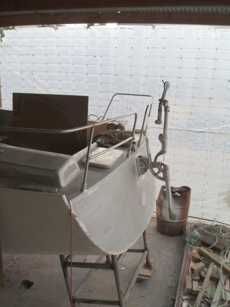
The steering vane and stainless railing were fitted.
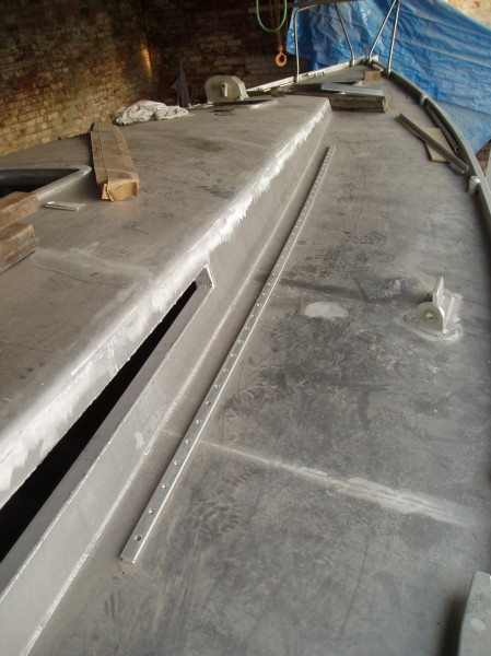
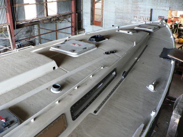
The deck plane was eventually sandblasted, sealed and faired, just like the hull earlier. Epoxy fillets were used extensively in the corners.

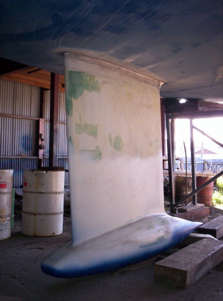
Using guide-coat (in blue) for sanding is extremely effective to obtain a near-perfect finish and highlight where to fill and where to sand.

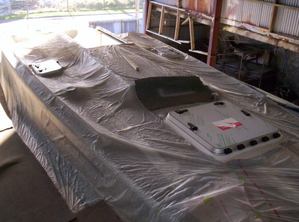
The sheet material deck thread is laid in place and cut to shape to fit around the deck hardware.
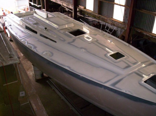
Finally, everything was removed and the deck topcoat was sprayed over all the areas that weren’t to be covered by non-skid matting. Keeping a wet edge when spraying a deck like that is just a notional concept, but with two people to assist and manage the air hose, there were no problems. The day was Christmas Eve.
The deck was masked carefully and preparations for topcoating the hull began. The topsides were sanded and sprayed with a grey undercoat and the white boot top was then sprayed on its own.

The hull was masked above the boot top once the coating could stand taping and the topcoat was sprayed on.
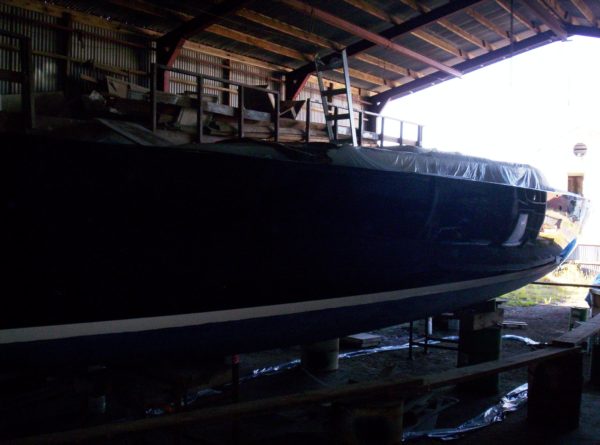
The transformation was little short of spectacular! A year or so out on the water does resolve this issue to some extent.
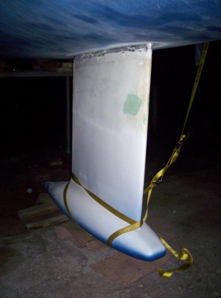
Back to serious considerations. The hull was lifted considerably, the keel driven underneath with the help of a forklift and the shell was then lowered on top of the foil. As the socket had been fitted earlier, the operation was quite straightforward.
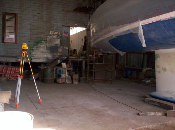
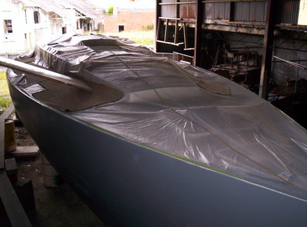
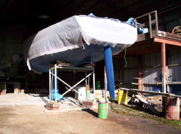
A laser level was used to check the position of the waterline. Covering the topsides offered some protection to the new coating, but even more so against incessant questions about the launching date.
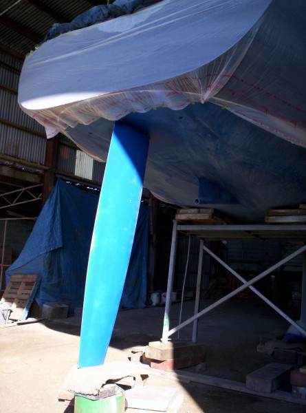
The rudder was also inserted into place to confirm the keel positioning. No room for error there.
The keel was finally welded into place with the utmost precautions, starting from all the structural welds inside and finishing with the hull plating – just to keep the water out.
The keel/hull joint was painted, faired and a light coat of antifouling applied to the whole keel. Standing a lot taller now.
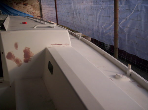
Back on deck, the masking started coming off and hatches were installed to close the concealed openings. I did manage to put one whole leg into one of them once before that. In hindsight, it was unnecessary.
The deck thread was then bonded into place. Hatches, windows and deck hardware were installed to stay.
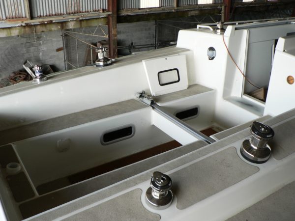
Winches and compass follow. The companionway washboards made of foam core and fibreglass were spray painted in the same time as the deck.
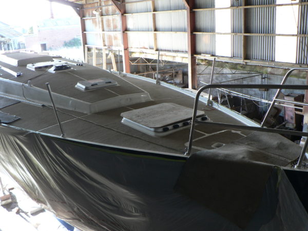
Pulpit and stanchions were finally installed.
Construction of the interior is described on the next page.
Hi Eric,
Can I assume from the phrase “all the structural welds inside”, that the foil was not a simple insert into a collar within the floors welded ‘top and bottom’. One of your Interior Construction photos reveals the doubled-up floors in the keel area and I wonder if the foil was attached by welding the floor cut-outs directly to it?
Was there any additional floor strengthening in the keel area?
And did you have to re-inforce the top of the foil to ‘smooth’ the load path?
Thanks – Peter
Peter,
The foil runs through the hull skin (itself thicker in the way of the keel) and is directly welded into the floors themselves. There is no collar or “fastening” arrangement. Once the keel was fully welded, the floors were doubled up around the keel attachment welds, bringing the total metal thickness to 16mm. This was entirely above and beyond structural requirements by the way.
There are additional intermediate floors at 250mm spacing in the way of the keel, tied into the main longitudinal girders. The foil is strong enough throughout to handle the root stresses, which are very well distributed. The keel design is the very wrong place to try and save a few kilograms.
The whole structural arrangement was calculated in three different ways for cross-checking the results, including running full FEA at 90 degrees heel angle, followed by fatigue calculations. Later, when the ISO12215-9 keel structural standard was released, the stresses were compared against it by curiosity and were fine, unsurprisingly.
If one thing can kill you offshore, dropping the keel is certainly it.
Best regards,
Eric
Hi Eric,
Looking at that last photo above I’m wondering how you get on going forward in a blow? The coachroof handrail stops beside the chain plates and then there’s nothing to hang on to between the forward lowers and the pulpit.
And I’m intrigued by your flush chain locker hatch. Is that a hole for the rode and therefore is the locker self-draining?
Thanks – Peter
Peter,
You just follow the lifelines on the windward side after the forward lowers and keep low down. The lifelines are 600mm high and the deck has a substantial toe rail. I didn’t want to extend the handrails into the walking areas, they become very dangerous trip hazards.
The chain locker is self-draining indeed and the anchor comes off the windlass and goes inside the locker if any weather can be expected, so the chain needs a way to make it into the flush deck hatch. There is a plywood/glass epoxy sole inside to keep the chain away from the aluminium and help with spreading the weight.
Regards,
Eric
Hi Eric,
Can you describe Nordkyn’s windlass?
Thanks – Peter
Peter,
It is a Muir HM1200 set up to run 12 or 13mm DIN766 chain (both have the same pitch). It had gone out of production when I wanted it, but the folks at Muir’s in Tasmania were most obliging and gave me an address in South Australia where I was able to find one and then they provided me with the gypsy I needed.
Eric
Hi Eric,
How did you fasten the winch bases and other deck fittings, particularly with regard to corrosion?
Thanks – Peter
Peter,
They are all through-bolted in stainless steel, but sitting on plastic pads with sealant. The bolts are bushed and insulated from the alloy. Worst thing you can do is tapping into the aluminium: after a few years, you will shear the bolt trying to turn it.
When access from the inside was going to be a problem afterwards, I sometimes installed insulated stainless plates inside and bolts go into this.
Regards,
Eric
Thanks for that Eric but I’m not clear about that last sentence. Do you mean you tapped the holes in the attachment plates and threaded the bolts into them?
Cheers – Peter
Peter,
In some instances, I spot welded stainless nuts onto the plate, because I didn’t want to make the whole plate that thick and heavy. When it was M6 only, then I tapped into the stainless indeed.
Regards,
Eric
Hi Eric,
Looking at the two photos above of the foredeck (and others showing the forebody from below), it’s clear that Nordkyn is full-sectioned forward above the waterline and yet you claim she has a “fine entry”. How do you define that term given that her forward waterlines can’t be that “sharp”?
And what’s with fine entries anyway? Are they proven to offer less resistance over a vessel’s entire speed range or do they only come into their own at higher speeds?
Cheers – Peter
Peter,
The hull certainly looks fuller forward at deck level for sure, but at the waterline, you can draw a near straight line a long way back from the bow and the waterline beam is noticeably narrower than the hull beam, so the hull is quite fine forward in most circumstances. What I didn’t want was a lack of volume forward leading to burying the bow because it is dangerous.
An interesting study was carried out at Delft Technical University to quantify the relation between the added resistance in waves vs the risk of burying the bow. It showed that more volume further up into the topsides added a little extra resistance in waves indeed, but – more importantly – it also significantly reduced the risk of driving the foredeck under.
The flare in the topsides of this hull forward does a spectacular job of keeping the deck dry when punching.
A fine entry is useful for as long as the hull operates in pure displacement mode, i.e. it doesn’t try to lift and plane. If the idea is getting the boat on the plane, then lightweight is everything and the hull entry is commonly a lot more blunt, because maintaining a lot of buoyancy forward is essential when hitting waves at high speeds.
Nordkyn is an ocean cruising yacht and is not that light. It used to be quite light in the early days when a lot of gear hadn’t yet made its way on board and would lift the bow and try to get on the plane quite easily, breaking the water at the mast in some occasions. It takes a bit to get used to it in the beginning.
Now, in ocean cruising trim, this doesn’t happen any more. The interesting part is that I still hit the same top speeds, but the hull works differently and stays trimmed flat.
This has in fact been so interesting that it became the topic of a research project to create extremely fast and economical pure displacement hull forms for applications like fishing or cruising launches – but this is another story I will almost certainly write about at some point in the future.
Best regards,
Eric
Alloy boat owners complain bitterly about the work needed to keep the paint on, How is your paint holding up, and how much upkeep has it required?
What do you think of Vinyl wrap as an alternative to paint for aluminium boats?
Paul,
It has generally been a non-event for 10 years, except on deck on and near the chainplates and the bow roller because of the stainless steel pins. I painted the metal of the hull with International Interprime 820, very costly product, but the best. On deck I used International Interprotect and it has been very good, but I have touched up the odd blister. If I was going to do it all again, I would look for better ways to fully insulate the stainless steel from the aluminium and I would definitely anodise the chainplates and cathead before welding them in. I would possibly make solid high-tensile aluminium stanchions too so they don’t need to be bushed with plastic and insulated.
The problems are not related to the aluminium, but installation/construction where other metals need to be used.
Kind regards,
Eric
I love your dry humor … “just to keep the water out.”