
Last Updated on 18 April 2025 by Eric Bretscher
In this article, we have a look at the Volvo Penta MDI electronic black box while relocating it off the side of a Volvo Penta D2-40B engine in order to protect it from the heat and vibrations.
IF YOU OWN A FAILED MDI BOX, PLEASE CONSIDER SENDING US PHOTOS OF THE INSIDE AFTER LIFTING THE LID! There have been many revisions of the module and it would be extremely interesting to see what design changes were made.
Background
Volvo Penta began the release of the current D-Series marine diesel engines around 2006. While all the larger models are common-rail, fuel injected electronic engines, the smaller D1- and D2-series engines, up to 4 cylinders and 75HP, still operate with traditional mechanical injection pumps. Volvo elected to interface these engines to its electronic gauges and controls by using an electronic interface module: the MDI (Mechanical Diesel Interface) black box. For some owners at least, the MDI box rapidly gained fame as the least reliable part of an otherwise excellent engine.

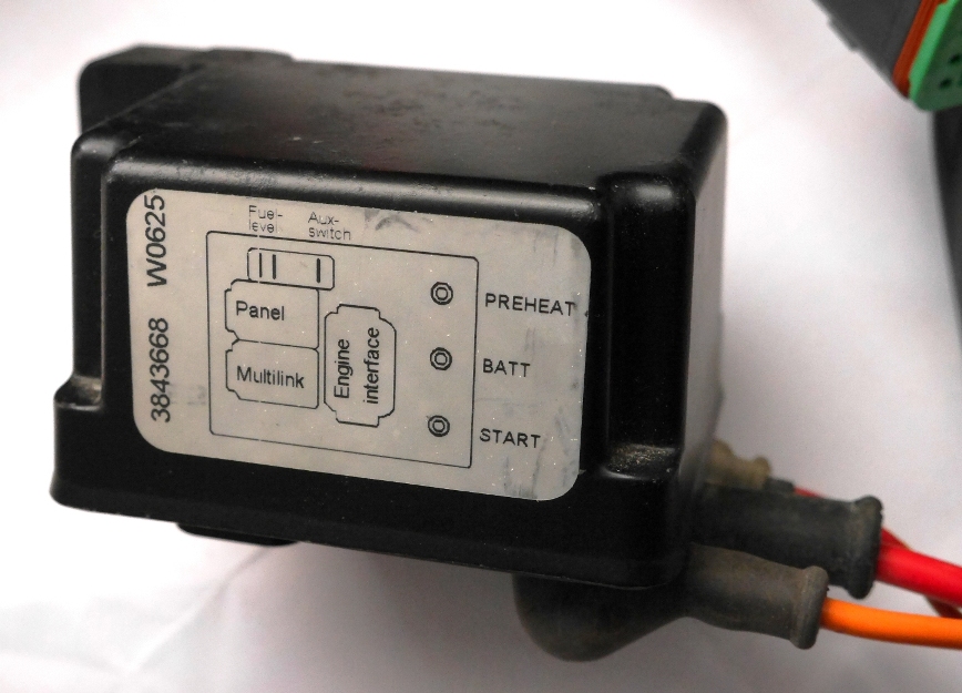
The Volvo Penta MDI black box once separated from the engine and most of the wiring harness.
The MDI box has had a surprisingly long revision history over the years, aimed at addressing failure modes and on-going reliability issues, with some versions recording high failure rates. The table below, compiled from publicly available information, shows the consecutive model numbers and approximate year of release, when it could be determined.
| Volvo Part Number | Year released |
| 3843668 | 2006 |
| 3885724 | |
| 21120710 | 2007 |
| 21261871 | |
| 21511215 | |
| 21558929 | 2011 |
| 21558939 | |
| 22458451 | 2015 |
| 22458451-P | 2017 |
| 22594274 | |
| 23195776 | 2017 |
| (23231607) | 2019 |
| 24743026 | 2025 |
It is interesting to point out that very few modules labelled 23231607 appear to have ever shipped. Volvo was shipping part number 23195776 in boxes marked 23231607 for some time. Some of these early 23195776 units were the object of a replacement campaign initiated in April 2018 due to erratic behaviour. A wider replacement campaign was initiated in August 2023 for modules with P/N 22458451-P, 22594274, 23195776 and 23231607, also due to erratic behaviour, and is open until the end of November 2030. As usual, only specific engines are affected and owners need to check with a service agent.
Until now (2025), the part number was followed by a manufacturing date code starting with “W” followed by 4 digits yyww, where yy = last two digits of the year of manufacture and ww = number of the week of manufacture. “W1128”, as shown in the photo below, indicates a module manufactured in the 28th week of 2011. This practice seems to have been discontinued on model 24743026.
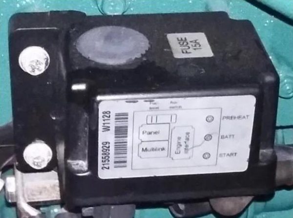
By 2011 already, a 15A blade fuse was added to the MDI box, protected by a sealed rubber cover.
Functionality
The role of the MDI box is largely a supervisory one in the sense that it reads all the engine sensors and outputs the information over CANbus for the Volvo EVC gauge/display system, but it does have a minor control function: it switches the engine glow plugs, the starter motor solenoid, the fuel stop solenoid and it energises the alternator about one second after the engine has started. A failure of the MDI box leaves the engine dead, but it can be bypassed very easily to preheat and start using a simple jumper cable or even a screwdriver, with some caution. The key issue is the lack of monitoring over coolant temperature and oil pressure afterwards. In fact, should the concern of being unable to start the engine be acute enough, one could opt to install an independent parallel engine start circuit by adding two external relays to connect the “PREHEAT” and “START” terminals to the “BATT” terminal at the push of a button. In this case, the preheating relay must be able to handle a current of about 10A per glow plug, so 40A on a 4-cylinder engine. Briefly applying power to the “D” terminal post of the alternator after the engine has started will cause it to begin charging normally, but increasing RPMs can be enough to achieve the same, due to the residual magnetism normally present in the rotor.
Reliability Factors: Heat and Vibration
The MDI box is factory-mounted to the side of the water-cooled exhaust manifold. When the engine has been running for some time, its temperature is approximately equal to that of the coolant: too hot to keep a hand on it. Furthermore, it is hard-mounted to the manifold casting and fully exposed to the vibrations of the engine.

Volvo Penta D2-40 engine in its factory configuration with the MDI black box attached to the water-cooled exhaust manifold. Note that this photo shows no extra length in the wiring harness to the MDI box.
High heat and vibrations are two well-known root causes of premature failure for electronics. Heat causes electrolytic capacitors to age and fail. Vibrations lead to solder joints cracking around the wires of trough-hole components and can also cause the quartz crystal of the oscillator to fail. I make little use of the engine and I very rarely run it for any amount of time; this may be why I never experienced any issues with my early model MDI box in 10 years and 230 engine hours. Nevertheless, I always had in mind to relocate it off the engine block to prevent a failure.
Relocating the MDI Box off the Engine Block
A preliminary investigation some time ago had shown that the wiring harness connecting the sensors around the engine to the MDI box was generally long enough to allow remote-mounting the box on the sidewall of the engine compartment, thanks to some extra length in the loom bundled with plastic cable ties. In fact, this extra length almost suggested that relocating the MDI box off the engine had been made possible and favoured by design, at least on early engines. This didn’t come as a complete surprise as it was not the first instance where I discovered understated, unadvertised superior engineering on a Volvo Penta engine: another one is remote voltage sensing for the alternator. I would have otherwise extended the cabling by cutting it and splicing it, or better by constructing an extension cable using male and female 8-pin Deutsch connectors.

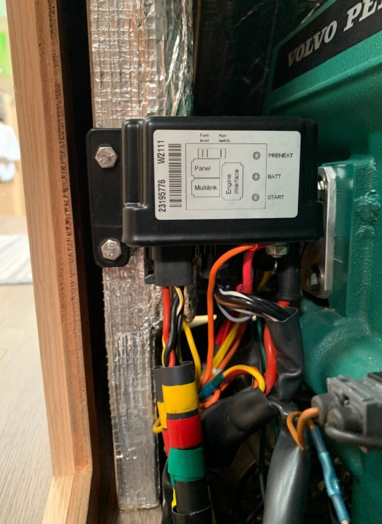
Volvo Penta D2-40 engine with MDI black box relocated off the engine to protect it from the heat and vibrations.
I constructed a plywood pad fitted with two M6 studs and epoxy-glued it to the sidewall of the engine compartment to support the MDI box. I also had to accommodate a few other constraints, namely the lengths of the Multilink cable feeding the EVC gauges and the cable to the EVC control panel, as well as the presence of an access panel immediately to the side of the engine. I moved the MDI box down and back to a location close to the rear engine mount, quite low. A low location may be more prone to see water in a rare and improbable event, but it is generally also cooler too and I decided this would be adequate. I only had to lengthen the coolant temperature sensor wire and I was otherwise able to re-route the loom without issues.
Relocating the MDI module off the engine block can be a simple matter of rotating it and refastening it to the side of the engine bay, as on this D2-60 engine, with minimal disturbance to the cabling.
Reliability Factors: Electrical
Many failures, and especially short-term failures, instead have electrical root causes except for some rare instances where engines shipped with clearly defective MDI modules. Some early versions would have failed from exposure to the back EMF of the engine stop solenoid. This can be prevented by adding a diode over the device to short the negative spike out and this is an electrical alteration I will carry out at some point (or I will trace the wiring and add it within the module if not already there).
Many failures of the module, perceived or real, have in fact been caused by poor connections to the battery: a high resistance path causes the voltage to drop whenever the starter solenoid and motor are energised, which can easily cause the electronics to reset and lead to starting problems. A negative voltage spike is also induced into the engine electrical system each time at the end of cranking. It normally has very little effect because the very low impedance of the battery absorbs it, but if the battery is poorly connected, it can lead to high reverse voltages appearing at the MDI box supply. This has demonstrably killed many, many modules, sometimes several in succession, with the blame usually going towards the black box and Volvo Penta, when it is in fact an installation problem. Use batteries with threaded studs, quality battery disconnect switches and ensure that all the connections are clean, free of corrosion and tightly bolted.
Don’t even think about replacing a failed module until the path to the battery is above any suspicion, or you will likely lose the next one as well
It also pays to remember that, in the factory configuration, the alternator charges into the main positive supply terminal at the starter solenoid. Anything less than a solid, uninterrupted connection of the engine to the battery while the alternator is charging will cause the voltage of the engine electrical system to spike up with the risk of destroying the MDI module.
Some modules were also lost due to the addition of ground disconnect relays to the installation on alloy boats because of the unclamped back EMF of the relay coil.
Pathways Following an MDI Box Failure
In the light of the poor reputation of the Volvo Penta MDI black box, I always wondered what I would actually do if I faced such a failure, remembering that both reliability and maintainability are important to me in the context of ocean cruising in remote places. I envisioned a few pathways, listed below in decreasing order of desirability:
- Repairing the module, if possible. With an electronic engineering background, this is always the first consideration that comes to mind. The root cause of the failure, once identified, should be addressed however.
- Doing away with the Volvo Penta EVC instruments system once and for good. This would require installing standard automotive gauges for coolant temperature, oil pressure and engine speed, as well as a few stand-alone switches and relays to deal with the glow plugs, starter and electric stop. An alarm circuit responding to low oil pressure or high coolant temperature would be essential too.
- Developing an equivalent replacement module. This would represent more work, but a better third-party open-source module would clearly have a market. Rather than using networked gauges on CANbus, a simple LCD display could present all the information. Such a module could be much simpler than the Volvo MDI box, which is clearly inheriting technology from the ECUs of the larger electronic engines in the range.
- Replacing the module, which is as easy as it is costly, but there are many reports of people having gone through more than one module, because replacement alone obviously failed to address the root cause. This would hardly be satisfactory. The failure rate of the modules has very significantly dropped since late 2019 however.
Option 2 has always been highly desirable in my eyes, because it would replace a proprietary system with one that is standard and fully maintainable at low cost, more or less anywhere in the world. The field of engine instrumentation seems to be split between European and American standards. Here, any such solution would rely on European gauges (such as VDO for example) and the only challenge would be identifying the factory-installed sensors to select compatible gauges.
Option 3 would be a lot more fun and cheaper than purchasing new gauges, as long as the time required for development is no object. This is often the case while cruising however.
Would the Volvo Penta MDI Box Be Repairable?
While I had the MDI box off the engine and well accessible, I couldn’t resist investigating to what extent a failure would be repairable for my own forward planning; this hinged upon whether the electronics inside were encapsulated or not. I started by unplugging all the multi-core cables to facilitate handling, but I left the three bolted heavy wires in place. The housing is made out of aluminium, but the base plate accepting the connectors is moulded black plastic, held in place by four Torx T-10 screws. A compression rubber seal is present between the two parts. Removing the screws presented no difficulty and then the aluminium cover separated effortlessly.
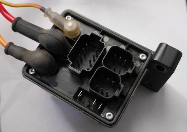
The underside of the Volvo Penta MDI black box reveals three sockets for Deutsch sealed connectors and terminal posts for the battery supply and cables to the glow plugs and the starter motor solenoid. This base plate is held in place by four Torx T-10 screws.
Underneath the cover, I was very pleased to discover two stacked circuit boards and no potting compound whatsoever. The fully sealed nature of the enclosure also means that the circuit boards are not coated and could easily be worked on if necessary (later versions of the module are now using coated PCBs). The top board contains two 40A-rated relays switching the preheat circuit and the starter solenoid (these relays have since been replaced with solid-state switching). It also includes the power supply for the electronics and additional circuitry with a IRF4905 P-channel MOSFET transistor likely related to the alternator D+ connection, but I didn’t formally trace this. The supply for the logic circuits appears to start from a NCV4269 5-volt linear regulator. The key point of interest here is two electrolytic capacitors rated 220μF / 63V in the power supply section, because these components are well-known to age faster and fail early when exposed to heat. This would make them prime suspects in case of black box failure, because a degradation of these capacitors would result in poor filtering of the electrical noise from the alternator and this could ultimately affect voltage regulation and the operation of the CPU. Here, the capacitors appeared in good condition, without signs of swelling or electrolyte leakage. As far as components go, everything else in the design of the MDI module should generally prove quite durable and resilient. The other enemy of electronics is vibrations and, here, in the absence of encapsulation, some of the larger components in particular could be prone to cracking of the solder joints over time. The large black power resistor mounted off the circuit board is a prime candidate for this; it has since been replaced by a series of surface-mounted resistors on newer modules.
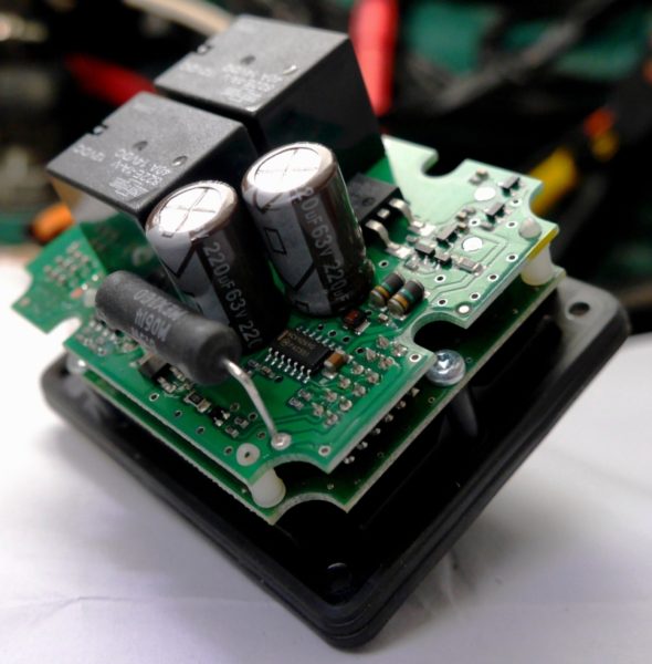
Removing the lid of the Volvo Penta MDI black box reveals two stacked circuit boards. The top board contains relays and transistors for power switching, as well as the power supply section with two electrolytic capacitors and a 5V regulator.
The bottom circuit board is the control board, which communicates with the upper board through a 12-pin pluggable header arrangement. While I didn’t attempt a complete tear-down of the MDI box, it seems that separating and extracting the top board should be quite easy after disconnecting the three heavy-current terminal posts. This would give access to the solder points to replace the capacitors or even the relays if it ever proved necessary.
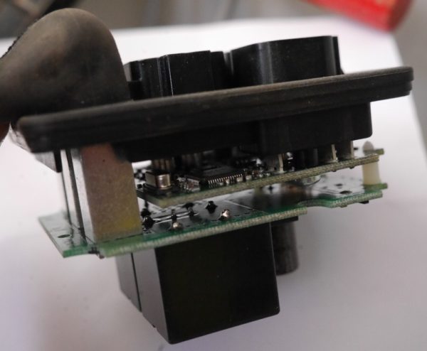
The heavy current terminal posts on the left connect directly to the switching board. The control board is hidden underneath it with the CPU and crystal oscillator well visible near its edges.
The bottom circuit board carries the CPU and crystal as well as more interfacing components to deal with the sensor signals and the CANbus interface to the gauges. The pins engaging into the sealed Deutsch connectors of the MDI box are soldered to it and they just pull through the plastic baseplate, same for the auxiliary flat blade terminals. The fact that both circuit boards are mounted back-to-back means that extracting the stack is enough to gain access to the components side of both boards without having to separate them. Not dismantling the module only affords a limited view of the logic board: the Philips/NXP-branded CPU is a LPC2119 microcontroller with 64kB of flash memory, quite a powerful 32-bit processor built on an ARM7 core with 2 CANbus interfaces and a fast 10-bit analog/digital converter. The crystal frequency is 10MHz.

The CPU used in the Volvo Penta MDI black box is a LPC2119 microcontroller with 64kB of flash memory.
Conclusion
While I took a while before finally relocating the MDI black box off the side of the engine, it should clearly be the first thing done when installing these engines. The presence of electrolytic capacitors in the module looks like a recipe for trouble, even though such capacitors can technically be rated for service lives in the thousands of hours at the temperatures considered. In all cases, the combined exposure to vibrations and thermal stresses promotes the breaking of solder joints over time.
Fortunately, the construction of the MDI box allows access to the electronics. Component replacement or even reflowing the solder over the boards appears perfectly achievable, so a failed module could be repaired. If this was not successful, a replacement module should arguably be able to offer a long service life, provided it is installed in a protected location. The fact that the electronics are not encapsulated makes them both repairable and more vulnerable to failure from exposure to vibrations.
In case of failure, replacing the whole Volvo Penta EVC monitoring system with conventional gauges may not be more costly (in terms of materials) than replacing the MDI black box and doing so would eliminate any reliability issues once and forever.
Thank you for this interesting and informative article.
On my D2-75F, the +12V power supply to the MDI is sourced from the starter motor rather than from the battery. This would seem to make the unit vulnerable to voltage transients owing to the inductance of the starter motor. When you looked within the MDI, did there appear to be adequate protection in the MDI box against such transients?
Dear Jeremy,
As the only supply from the battery is terminated at the starter motor solenoid, this is likely to be valid for all the engines using the MDI module.
Looking at some of the key components like the NCV4269 linear voltage regulator producing the 5VDC supply, and the 63V-rated filter capacitors, the module seems to have been designed around a 60V peak supply voltage limit. A number of other parts I identified had higher voltage ratings. I didn’t find any large capacity transient voltage suppressors anywhere, so it seems quite clear that Volvo opted to design for a sufficiently high peak voltage and I also think it is the most robust option in this context. 60V should be ample considering that the cables to the battery are normally both quite short and substantial. Longer and/or undersized cables could allow the voltage to spike more at the engine, but even then the available margin seems quite considerable.
One potential scenario that could lead to the electrical destruction the MDI box is an alternator load dump caused by the loss of the battery while charging at high current. In this case, the surge could easily exceed 60V, especially with the standard Volvo wiring which also connects the alternator output (B+) to the started motor solenoid.
In most cases, it makes sense to run a new dedicated heavy cable from the alternator B+ post to the battery, or – better – to a battery isolator for charging separate banks. This normally mitigates or even entirely eliminates this possibility.
Kind regards,
Eric
Great ideas about the MDI box, thanks!
The LCD panel on the MDI Panel Tach module (VP p/n 21628160) on my VP D1-30B has failed. I would like to replace just the LCD module a la the old VDO tachs but am having a very hard time finding any reference to source the part. Can you help?
Hello Royce,
The link between the MDI box and the EVC tachometer (Volvo Penta Multilink cable) uses the J/1939 automotive protocol over CANbus. It should generally be possible to replace the EVC tachometer with a generic J/1939 engine data display (search for J1939 display). Another way is bridging the data to NMEA2000 and display it with other marine data, but this is more suitable for vessels already using a NMEA2000 instrument system.
You can find information about bridging and the messages used by the Volvo Penta EVC engines (to assess display compatibility) here: https://www.yachtd.com/news/j1939_volvo_penta_evc_gateway.html.
Kind regards,
Eric
Thanks for the article, I am on my Third MDI, Two were replaced by the previous owner and 1 by me and I only have a total of 150 hours on the Volvo Penta 55s. I like the idea of relocating the MDIs away from the Engine and will look into the feasibility on my boat.
You did mention the ability in a crisis to bypass the MDI as my Windlass would not work without the Starboard Engine I would be very interested in learning how to do that.
Stephen,
The article does describe how to start the engine without the MDI module: make an external connection between the “BATT” post and “PREHEAT” or “START” on the MDI box to respectively preheat and crank the engine.
Make sure all your windlass wiring originates from the battery and doesn’t under any circumstance go to the engine or share any current path with the engine cables. Each time you stop the windlass motor, a voltage spike is produced and it is essential that it is routed back directly to the battery where it can be absorbed.
Best regards,
Eric
Hello
after just 18h (8 quick sea trails and tests) of running our D2-60 the MDI box had to be replaced by Volvo. Do think in this short time the capacitors really could be a source of troubles? In our case it must be another “source of pain”. What do you think
Best regards
Lorenzo
Hello Lorenzo,
Clearly not, capacitor failure is a long-term ageing issue. Electronics are most likely to fail either in very early life (component or assembly defects) or from age-related problem after a duration depending on the environmental conditions.
I wouldn’t worry about it unless the replacement one also fails in short order, except if there is something unusual/abnormal in the wiring of your engine. Some people have reported MDI box failures in relation with ground-disconnect relays that were added into the standard wiring on metal boats. Electrically insulating the whole engine from the hull is a far more sensible and effective approach in this case…
Best regards,
Eric
Hi Eric,
Interesting article, thanks!
I have a 2006
Volvo Penta D2-55-C
868971
5103955405
It has the simple panel with tach, LCD engine hours (not working) and key on/off, the key also controls the glow plugs. The engine has a black box on the coolant side like the one in the picture. What I would like to do is get the engine data, RPM, temp, oil pressure to my iPad. Do I need to buy a penta MDI interface to do that? I have NMEA 2000 on the boat too.
Hello Mike,
You need a gateway to bridge from the J/1939 protocol used by Volvo Penta to NMEA2K. There are aftermarket devices to do that, like the one made by Yacht Devices (please note that I have never used or seen it however). Have a look and see what you can find.
Best regards,
Eric
Thanks, I’ll have a look at those.
My understanding is that the MDI module also controls the alternator output – no battery charge if bypassed. Is there a fix for this.
Hello Murray,
It is incorrect. The alternator is a standard alternator and it charges independently of the MDI module. The only thing the MDI module does is kick-start it about 1 second after the engine fires up. It does this by applying power to the D+ terminal of the alternator (where the charging light is traditionally connected).
An alternator that has been in service for a while normally has some residual magnetism in the rotor and will often self-excite and start charging by itself if you rev it up high enough.
However, a simple work-around for this is briefly applying battery voltage to the D+ terminal of the alternator and it will cause the alternator to excite and start charging. The D+ terminal is a small threaded stud with one black wire attached to it and there is a “D” embossed in the backshell casting near it.
You have raised an interesting point, so I will have a look back at the text of the article and see if the matter should be mentioned there.
Thanks and kind regards,
Eric
Great post, thanks!
My D2-40 (from 2019 with 300 hours) blackbox failed yesterday after an dieselfilter/oilchange where I had to use many long attempts to get the engine running afterwards. Suddenly the panel went all black. I bypassed with an external startbutton and got it running. But my batteries would not charge what so ever, even after high rpms (2500).
So in my case the blackbox seemes to have to be working to start charging. What can be done to start the charging having bypassed the black box?
Regards Erik
Hello Erik,
You need to purge the fuel system from air bubbles after a filter change using the manual priming pump located on top of the secondary fuel filter before restarting, otherwise air will get to the injection pump and you might have to purge the injector lines.
Your case is interesting as you clearly killed your MDI box with the electrical transients generated by switching the solenoid/starter motor. Can you please post or e-mail me the Volvo Penta part number printed on it?
Anyway, the MDI box energises the D+ terminal on the alternator about 1 second after starting the engine to cause it to start charging. It is the small threaded stud with a single black wire attached to it. Just touch it with a wire at battery voltage and it will start charging immediately. If you are going to do away with the MDI box, then install a charging light (2W incandescent bulb typically, or a power resistor) between the engine “ignition” circuit and this terminal. The light will glow before the engine starts and go out as the alternator starts producing a voltage.
Kind regards,
Eric
Thanks for replying!
Today I got a new MDI box and installed it. After many attemps I got light to the LED display, and engine started. After a minute the battery symbol and alarm came on. I stopped and started and alarm came on again. The alternator was charging so its clearly a false alarm for some reason. Then I reved the engine to 1500 rpms and the temp and rpm gauges died, came back on and froze, and the display died. And that was it. No more life. Had to kill engine manually. Do you have any idea whats wrong? Some kind of electrical failure/overload/grounding fault into the MDI?
I’ll mail you the number for both MDI
Hello Erik,
I am quite concerned by your observations. The display should come on as you power up the EVC system and, if it doesn’t, it suggests a power supply issue like a bad electrical connection and the prime candidate is the cabling between the battery and the engine, or plugs not fully inserted into the MDI module.
Also note that the MDI module has two identical sockets labelled “Panel” and “Multilink”, which are physically interchangeable, but incompatible. I remember reading a report that swapping these plugs by mistake damaged the module.
I would find it very difficult to believe that Volvo shipped a new MDI module that would not readily power up and initialise the display properly.
When the alternator starts charging, the stator windings feed an AC voltage to the rectifiers connected to B+ and B-. A small secondary rectifier “duplicates” B+ on the D+ terminal to create a supply point that is only on when the alternator is charging (unlike B+ which is normally at battery voltage all the time). D+ is used to power the internal regulator and this means that the alternator remains dead until external power has been applied to D+ and then it produces its own.
The MDI box applies power to D+ after the engine starts, and then checks periodically that there is voltage on D+ to confirm that the alternator is running. You get a charging alarm if D+ has low voltage, but also if the system voltage exceeds a threshold (around 15V from memory).
The system died when you increased the alternator RPMs and this can only mean high voltage. There are two possible scenarios: either you damaged the alternator regulator when you were cranking and trying to restart the engine after the filter change, or you are sensing the charge voltage at the battery with the alternator and there is a bad connection in the positive between the engine and the battery. Electrical damage from transients from cranking should not be able to happen if the battery cabling is heavy and the connections are good, so I suspect something is not right there. This would also explain issues with powering up the EVC system and the MDI box failed as a consequence of something else, not in itself.
It was a mistake to start the engine when things were not powering up and behaving properly in the first place, because if there are such issues, starting the engine is not going to help. If you are lucky, the MDI module will have protected the EVC gauges.
This would not be the first time I hear about repeated failures of the MDI box because of a bad battery connection. In one instance, the battery disconnect switch was eventually found to be faulty.
Kind regards,
Eric
Hello Eric. Thank you for all your research and commentary. I own a couple D1-30F engines on a catamaran sailboat. I was part of the engine recall program. Since February 2018, I have replaced 5 MDI boxes between the two engines. The first failure didn’t make 2 minutes. Outside of the obvious concerns I’m wondering why VP engineering has not resolved the matter. Beyond them? Your article mentioned vibration and temp issues. My original engines since 2009 had accumulated 880 hours and ran flawlessly with no MDI issues. I think whatever they did electrically
to bring the new engines into compliance has generated the issue. I’m not an electronic engineer but I believe there’s a sequencing issue that they can’t overcome without a broader look at components in the system all the way to ground. They’ve tried to put a bandaid on this issue since day one. Nobody’s screaming at this moment because they’ve been very generous with replacement parts. But that doesn’t speak to the known defect and safety issue of engine shutdown on waterways or oceans.
I did read a commentary from someone that indicated that a technician told him that they are stressed over 13.8 volts so essentially any craft with mppt charging might be suspect as to cause of failure. Of course, as the writer indicated, it would be difficult for VP to get around their generator output of 14.2-14.3 volts. So essentially, mppt charging systems with equalizing voltages would void your warranty if that were true. Hmmmmmm…. now there’s a new twist for VP owners and long term boating. Maybe we all ought’a get ourselves some buck converters and jump in.
So thanks again Eric and if you come up with an engineered fix, please share.
KJ
Hello KJ,
There is no doubt that a number of the failures experienced by people, and especially the short-term ones, have had an electrical root cause, rather than premature ageing due to heat and vibrations. My point here is that an electrically sound unit will have a reduced life expectancy if it is left installed on the engine block itself.
I don’t believe for a second the tale about the 13.8V voltage limit. Not only it makes no sense, but it is idiotic when you consider it from a component rating and electronic design point of view. I know that the back EMF from the fuel cut-off solenoid when the engine is stopped has been blamed to cause failures at sme point and this would have been corrected (by adding a free-wheeling diode obviously). Other failures have been related to “unexpected” installation practices using contactors to disconnect the engine ground when it stops etc. This can cause a negative voltage spike in the engine electrical system. Failures of the mechanical relays were also occasionally reported, but this seemed uncommon and it is trivial to fix. Any disconnection of the battery while the engine is running would almost certainly take out the MDI box before even damaging the alternator and this may have happened in some cases with bad battery switches.
I have been considering adding a free-wheeling diode to the fuel stop solenoid because it can’t do any harm, but it is generally difficult to propose any improvements to the electronics, because there are so many versions of them and the differences between them are obscure. I wish I had an opportunity to open and inspect the latest model, assuming they haven’t potted the PCBs in resin by now.
Some revisions of the MDI black box proved to be worse than the versions they were supposed to replace and led to yet another hardware revision. I am also puzzled by the fact that Volvo Penta have been struggling with this issue for that long considering that we had reliable engine control modules (ECM) before these D-Series engines were even brought to the market, but these are not constructed like the MDI black box.
Remember also that the MDI box has zero control over the operation of the engine itself once it is running. On these engines, emissions control and regulatory compliance are entirely met by the mechanical injection system and thermostat. The only driver behind the many revisions of the module has been reliability.
Kind regards,
Eric
Hello,
Thank for posting a very interesting article. I have one of the latest versions of the MDI, replaced as a part of the recall campaign in the autumn 2018 at the time I bought the D2-40F. This engine has been working flawlessly for 65h, but now the preheating fails. I have not yet opened the MDI but will do so, and if necessary replace the relay (or add an external relay activated by a manual push-button and / or timer circuit). As far as I can see there are no potting in my MDI. Regarding heat as a root cause of the failures, I added a fan to the engine compartment last year since the generator seemed to become too hot (+90C?) during warm summer days after about an hour of running the engine, the MDI certainly got even warmer.
Jens in Sweden
Hello Jens,
Thank you for commenting on the build of recent MDI modules. The preheat circuit is extremely simple. If the relay failed after such a short time, it could be vibration-related as it is a mechanical component with a spring-loaded contact and plain bad luck. If they still use the same relay (Song Chuan 822E-1A, 12V coil), then it is available from Mouser Electronics for a few dollars under part number 893-822E-1AS12VDC. Please do send photos of the inside of the new module and the PCBs when you get in there.
The MDI module is mounted alongside the cylinders below the water-cooled exhaust manifold, which is one of the hottest parts of the engine block and a lot of the heat flows into it by conduction. The new D-Series engines also run hotter than the older models in order to achieve cleaner combustion.
Kind regards,
Eric
Hello Eric,
The design has indeed been revised: now the use solid-state relays / FET:s only, I will email a photo. I cannot find any bad solder points or obvious signs of damage or ageing. Possibly I will check if the preheat FET receives a gate voltage or not, and in that case I might replace the FET.
Jens
I have one of these in my boat. Part number 21558929. It has worled flawlessy for several years. One spring, after been on the hard for a whole season, the fuel was contaminated with water. That resulted in water in the fuel/injection system, causing sudden stop of the engine after just a minute. Didn’t know at that point it was water, not just air in the fuel lines. Probably the diesel in the fuel lines was ok, but when the engine sucked in the contaminated diesel it stopped. Then we suspected that water was the culprit. Emptying all the fuel, cleaned the fuel container/tank, fuel filter and refueled with fresh diesel. Bleed the fuel system, but still no start. It was probably still water in the fuel lines. Managed to get the water out of the system eventually. But in the process we accidently shorted the glow plug rail to ground. That caused a spark and the preheat / glow to not function anymore. The rest, instruments and starting was normal.
When inspecting the MDI box I encountered that one of the MOSfets didn’t measured the same as the three other. Ordered one new MOSfet (011N04L) and swapped it. It was difficult to desolder with just a soldering iron. In the process the soldering iron slipped and I ripped one SMD capacitor out of the circuit board. It seemed to have survived, as there was no destroyed traces and the capacitor also seemed ok. So I resoldered it.
But my soldering skills isn’t as good as I wished it was. At close inspection I saw a solder ball betwen the legs of the MOSfet, but as it was at the earth plane, and five of six legs where connected to gether anyway, I didn’t try to resolder. I probably should…
When connecting the box and all the wiring, we tried to start. That didn’t went well. The system alarmed instantly. And the glow plug rail showed 13 volt. Wich it shouldn’t have, as we haven’t pushed the preheat button yet. In just seconds I smelled burnt electronics (never good) and when I touched the MOSfet it was very hot. I measured it again, and now it was shorted.
I ordered two new MOSfets from Digi-key (fast shipping, just two days from US to Norway). I resoldered the new one, and now it measured the same as the three other.
Connected all together, but this time without connecting the preheat lead (the orange one). Turned on the main circuit, no smells. Turned on the display, and all seemed just fine. Still no smell. Shut it down after a few seconds without trying to neiother preheat or start. Pulled out the MDI box and touched the MOSfet. Not warm at all. Still measured as normal. So I put it all together one more time. All seemed ok still. But when I hit the start button (just to check if the starter solenoid kicked in) it just klicked. Not the solenoid, but something electronic, like a fuse or something. I smelled the MDI box yet again, but neither strange smell or hot components. Nothing visually abnormal either. Checked all the fuses I could find, all of them seemed ok. Tried one more time to put it together, but the display was dead. No life at all.
So what do I do now? Omit the MDI box and rely on old time simple relays, or buy a new MDI?
Hello Geir Andre,
Shorting the glow plug rail to the block will cause damage because this supply is not fused anywhere. The IPB011N04L MOSFETs are arranged in pairs in a somewhat surprising back-to-back series configuration, which means that they can also interrupt any current trying to flow back into the battery. A single MOSFET behaves like a forward-biased (i.e. conducting) diode in the presence of a current flowing backwards through it.
It could appear overly cautious, but Volvo Penta must have found a reason to adopt this design. Anyway, in the event of a short-circuit, the FETs have no other option than blowing like fuses and one in the pair will almost invariably fail before the other. The most immediate failure mode for MOSFETs is going into short-circuit first, so you could end up with one survivor and one open-circuit, or one shorted and one open-circuit. If you replaced the FET interrupting reverse current and the other one was shorted, then connecting the glow plugs would cause uncontrolled current to flow freely through the shorted FET and then backwards through the body diode of the new FET, dropping about 0.6V on the process. This will cause it to dissipate about 6W in heat per glow plug connected (about 10A current per plug on these engines and 0.6V drop over the transistor). This will cook it in very short order. In this case, you should have replaced the pair and everything should have come right.
MOSFETs can be difficult to test without first removing them from the circuit. A good transistor will read open circuit from the drain (tab) to the source (5 pins linked together) and like a diode from the source to the drain. The gate (leftmost pin) should be isolated from both the source and the drain.
The best way to remove SMD components is using a hot air soldering station. With a little bit of care, you can achieve the same with a heat gun on a low setting. You want to heat the parts and the board just enough to melt the solder and release the component. You can use aluminium foil to shield other parts of the board.
Reading about your last attempt, I wonder whether you successfully removed the short from the glow plug rail. Semiconductors can indeed emit a faint “ping” noise when switching a lot of current and the only part of the circuit capable of this is really around the 4 MOSFETs. I would use a heat gun and lift off at least the two MOSFETs switching the preheat (if not all four), then try the unit without them and the starter solenoid and glow plugs disconnected anyway. See if you can get the display back. If not, then further damage has occurred and you might have to consider one of the options discussed in the article above. You can manually switch the preheat and starter solenoid to get the engine running, but it wouldn’t be responsible to operate the engine without any monitoring on oil pressure and water temperature, so you should at least add these two gauges and an alternator charging light if you don’t replace the MDI box.
Kind regards,
Eric
Thanks for the great answer. 🙂
I found the reason why the display didn’t wake up. When we installed the battery, we forgot to tighten the terminals 🙁 When we tightened the terminals, the EVC display worked again. But the EVC beeps constantly. If I remember correctly, it is the system failure symbol.
Regarding the MOSFets, I ordered two new ones but did replace just one. So if I replace both the new ones, it might work? I’ll try it tomorrow. Crossing fingers and toes 🙂
Thanks 🙂
It would appear that the clicking noise you heard earlier could have been a spark at the loose battery terminal when the starter circuit was closed and that would be good news.
If you have a failed MOSFET in the pair, the system might well see it and report a system failure. You should not find battery voltage on the 5 pins linked together (source terminals) of the FETs when the battery supply is present and the FETs are supposed to be off. If you find battery voltage there, then the first FET must be shorted.
If you heat the board, you can just as well remove both transistors for a start and test them properly away from the circuit. You could also try to power up the module without them and see what the display looks like. You might only get an alarm when you try to preheat because it can’t switch the output on.
Best regards,
Eric
Regarding: “One could opt to install an independent parallel engine start circuit by adding two external relays to connect the “PREHEAT” and “START” terminals to the “BATT” terminal at the push of a button. In this case, the preheating relay must be able to handle a current of about 10A per glow plug, so 40A on a 4-cylinder engine.”
Are the preheating and start outputs of the MDI box just simple relays? I attempted to look up the part numbers “HAC728” without success to confirm. If so, there should be no harm or risk from applying power to those terminals (with harnesses still connected) using external backup relays, correct?
Hello Ken,
Early versions of the module used relays. Later they replaced these with MOSFET transistors in a configuration that fully isolates the terminal posts. In both cases, you can install a parallel control circuit without issues.
Can you please e-mail me a picture of the top board in your unit and the MDI box model number? I am curious about the HAC728 reference you are mentioning. It doesn’t match either design and I would like to confirm there was not an intermediate circuit with different components maybe.
Thanks and best regards,
Eric
Eric,
My MDI box failures have all involved the start-stop functionality: un-commanded stops, inability to stop, or inability to start. At all times, the J/1939 bus has continued to function (I have a J/1939 to N2k interface.)
How hard can it be for Volvo-Penta to take a button press on the panel and operate a relay in the MDI box to activate the stop solenoid or start solenoid, as appropriate? I realize it’s slightly more complicated because there’s some self-test circuitry involved too: for example, disconnecting the stop solenoid raises a periodic alarm.
I’ll take a photo for you of a failed 23195776 (shipped, incidentally in a box marked 23231607.) I’ll also do a few tests on it just to rule out the possibility that after all these failures the buttons on my panel haven’t worn out.
Jeremy,
Thank you for writing. Remember that the control functions of the MDI box are precisely limited to starting and stopping. It could have transient issues over CANbus like skipped or corrupt messages and they wouldn’t be visible. There have been many “dead” failures with these modules in the past as they seemed to suffer from electrical transients. Your feedback is interesting as it suggests that this would have been addressed by now. At least one relatively recent version was recalled as faulty and known to malfunction with the symptoms you describe.
I think that the module operates in relatively difficult conditions from an electrical point of view as it is exposed to the high frequency ripple voltage from the alternator (which, by default, feeds into the starter motor connection, not the battery) and spikes from various inductive loads. There is also a fair amount of attached wiring to pick up transients and feed them into the electronics. While the design and construction of the module have improved a little over the years, they are clearly not “heavy duty industrial” when it comes to the interface between the electronics and the outside world.
We also tend to focus on the physical module itself and the electronics, but some versions could just as well have experienced firmware problems as such embedded code is always very closely tied to the electronics.
When you open your 23195776 module, see if you can separate the PCBs if you get the opportunity and also take a picture of the lower one with the processor. At some stage, once I have a little more material available, I will write an article showing and discussing the differences between the models I have received photos for. The design has seen considerable changes over the years.
Thanks and kind regards,
Eric
Really appreciate your article re MDI for the D1/D2 Volvo Penta labeled diesels.
I have at least 1 more number 3885724. My engines are D1-30B circa 2006/2007. Not sure which but they apparently missed the engine recall either by date or the fact that they were on a European boat which I now own in the US.
Another puzzle piece. VP sends 23231607 labeled blue parts box with 23195776 labeled part inside. Their explanation per the local VP Certified business… 23231607 is a kit containing 23195776 and a pamphlet of instructions… $800 please (well, they haven’t said please).
Hello Martyn,
Thank you for the additional information, I have added it into the table. As I have never seen a picture of a MDI module labelled 23231607 and everybody reports receiving 23195776 in the box labelled 23231607, it could well be the explanation indeed.
This would make 23195776 the latest version and, as it has been around for a couple of years now, it may have proven more reliable. Still, I have received photos of the top PCB of 23195776 in failed units, so it may not be the end of this saga.
Kind regards,
Eric
I have a 2010 D2-55F with about 3500 hours and experienced the issues you refer to here.
Problems started in 2016 with a burnt out fuel solenoid. Was replaced and the replacement burnt out. It was then noticed that the Stop on the LCD was flicking on and off. The MDI was replaced. Within a few weeks we had surge problems caused by the stop solenoid being activated. Also problems with starting. Replaced the MDI again. Also failed, the Volvo dealer gave me their older test unit which I used for a month or so. They got a new revision which has been on for a couple of years without problem. So I probably have the 22594274.
I noticed there is a 2018 recall notice issued by Volvo for the MDIs. See https://i.imgur.com/YZmExSn.png. Will check with the dealership to see whether I should be upgrading. What I would really like is to have a spare given the horrible reliability.
Greg,
I am aware of the recall. It is quite specific and targets the latest F variant of the engines only, so they were replacing a defective version or even production batch within a version of the MDI module. This can happen. There have been a lot of problems with some versions of the MDI box, but others have also given good service, all have been known to fail and we automatically hear more about the failed ones…
Eric
I decided to check the panel on my Volvo D2 and found that the Stop button was not working. The MDI box that I thought had failed (23195776) is in fact working fine. I’d recommend checking the panel buttons in cases of stop/start problems even though the MDI box is the prime suspect.
Hi Eric,
As written in your article: Some modules were also lost due to the addition of ground disconnect relays to the installation on alloy boats because of the unclamped back EMF of the relay coil.
Now I an owner af an aluminium vessel with an D2-55F with ground connected to engine (2015). Without the MDI its much easier to install a additional ground isolation relay. With my engine and with the MDI I’m struggling how to do this. Please can you advise, how can I isolate the ground/ install an additional relays to minimize contact time with ground/engine (only starting/ glowing).
Regards, mike
Mike,
For a start, I can tell you what I did about it. I electrically insulated the engine block from the hull by mounting it on thick plastic plates and sleeving the engine mounts bolts. I also replaced the metal Morse cable fork on the gearbox control lever to prevent it from grounding the block at the engine controls. The throttle lever attachment already had insulation. If you don’t do that, you immediately set up a cast iron/aluminium battery cell with sea water as electrolyte, whether the ground is connected or not. Next, I used a plastic ball valve on the seawater intake, so it is not electrically conductive when shut. I also have a 2-pole battery switch to the engine and I turn this off when the engine is not running: it breaks both ground and positive supply. The only anode I have is on the propeller shaft to protect the propeller. I designed everything for zero corrosion and achieved zero corrosion.
Now, unless Volvo changed the design of the electrical system on newer engines, you can’t operate the MDI box without a grounded block because there is at least one single wire sensor (coolant temperature switch) that relies on a negative block to function, so you can only disconnect the block when the MDI “ignition” power is off.
If you do fit a ground disconnect relay, it is critical that there is a free-wheeling diode in parallel with the coil to short out the negative spike when you turn it off. I would also want to disconnect the alternator B- post from the block and run a new cable to the battery negative instead so you can’t lose that negative with the engine running. It could damage the alternator.
The control for the relay would have to come from the MDI power wire on the Multilink cable (but beware of the load increase), unless the whole MDI system was able to operate without reference to a negative block. If this was the case, then you would want to operate the relay using two “OR”-ing diodes from the preheat and start posts of the MDI box.
As far as I am concerned, a 2-pole battery switch is simpler and better. Disconnecting the engine ground stops grounding the hull through the block, but it doesn’t actually lead to a good outcome anyway if the hull and engine are electrically connected.
Kind regards,
Eric
Hi Eric,
Many thanks for your reply. In the meantime I have been in contact with Volvo Penta France. They do the installation/conversion for Aluminium Ovni boats. I received the electric drawings and part list to modify the engine with additional relais. MDI is not grounded during operation. There is only ground contact during start and preheat. Please drop me an email to share the information. Appreciate your feedback.
Regards, Mike
Hello Mike,
Then it will require an isolated water temperature sensor.
It still doesn’t resolve the galvanic corrosion cell problem if the engine block is electrically connected to the hull, but from Volvo’s point of view, your hull acts as a big aluminium anode protecting their engine, so it won’t worry them.
Kind regards,
Eric
Eric,
Thank you for the informative article on the Volvo MDI. Wiring information is incredibly difficult to find.
I have a D2-55F with OEM 115A alternator. Now upgrading to an alternator with external regulator. I’m getting an alarm at the EVC panel that I suspect is from incorrect interconnection between the new alternator/regulator the MDI. I’ve disconnected the yellow S wire as I can’t find its purpose for the new regulator. Would this generate the alarm?
Would you know the purpose of each wire between the MDI and the OEM alternator? According to the OEM Alternator schematics, they are labeled D, S, and W. B+ and B- are self-explanatory.
Heins,
You are downgrading your alternator and it is an immensely stupid thing to do. This was the driver for developing the VRC-200 controller, it just makes the excellent existing alternator fully programmable.
“S” is the alternator voltage sensing input and if you run a wire from there directly to the battery positive, charging performance will probably increase enormously. Connect “S” to a VRC-200 controller instead and then you can configure any charge profile you want.
“D” powers the internal regulator. The MDI box applies power to it initially through a small black wire to kickstart the alternator after cranking and then it is monitored for voltage. If that wire doesn’t have power when the engine is running and the battery voltage is below a threshold, the EVC is going to alarm on alternator failure.
Bare alternators sold without regulator have no D terminal. If you connect the black wire somewhere else (like B+) to try to get rid of the alarm, you will need to check that this doesn’t drain the battery when the engine is off and the MDI box could then complain that D has power before the engine starts, when it shouldn’t.
“W” is an AC output to drive a tachometer, you don’t need to worry about it.
Kind regards,
Eric
Eric,
Thank you for the fantastic work you do.
I have an odd start problem with my D2-40B, serial 5102001879. After 11 years w/o problems it began this summer to fail to start when finishing sailing w sails. When pressing the start button the power simply cuts. A few time it starts after power up the power button on the panel, but else I have to switch the main engine breaker downstairs of and on. Hereafter it starts w/o problem.
When it fails to start there is no power from MDI to the starter relay (I put a lamp on). Other panel functions like engine stop, engine alarms, power up etc also works fine. (The neutral switch is apparently not active, I can start in gear, but has always been so).
The MDI Volvo part number is 3885724, i.e. one of the old ones.
I can’t figure out what it mean that I have to cut the engine main to reset the system. My best guess is something to do with the MDI box. Have you any suggestions?
Best regards
Henrik Holten Møller
Henrik,
Thank you for your message. My guess, considering the age of your MDI box, would be that the electrolytic capacitors on the top PCB have dried out. They are no longer able to act as a buffer during the transients caused by the chain of events leading to engaging the starter solenoid and it causes the CPU to crash/lock up at times. When this happens, you have to turn the power off completely to reset it.
Your MDI box is the next version after mine. It should not be very different inside than the one I show on the photos in the article, with two 220uF/63V electrolytic capacitors. I would open the MDI box, separate the top PCB and replace the capacitors with new ones. It is an easy thing to do with just a soldering iron. Use good quality capacitors with a life rated at 105degC. Please send some photos if you get a chance, this is a model number I have never seen open.
Kind regards,
Eric
Thanks Eric. Interesting, I will start right away.
Rgds Henrik
I had the same problem. I traced it a bad battery cutoff switch. I changed out the switch and no problems now.
Yes, this would certainly do as well. Excessive voltage drop during cranking.
Hi Eric,
How do I separate the 12 pin connection between the boards in the capacitor end? Pull apart or de-solder? They seem very tight and I’m afraid to damage connection and boards.
Rgds Henrik
Enjoyed reading your analysis. I have the D2-55F that installed in a Slocum 43 (circa 2016). From the start I had issue with EVI guages as the voltage meter was constantly out… although the NMEA 2000 read out on the Garmin MFD read correctly. ….The dealers solution was to replace the MDI ! .. clearly that didn’t fix the issue. VP has been unwilling or unable to provide a correctly scaled Voltage meter. The following year the replaced MDI simply failed to light up (and the engine wouldn’t start) Replacing that one did fix the problem until June this year… and another one was sent fixing the problem … until last week, after 6 weeks of not being on the boat (hip replaced) . I engaged the connection switch and the engines hours immediately showed and when I hit the ON button (not the START button) the engine started immediately! I let the engine run until the engine reached engine temperature…. and I hit the STOP button until the engine stopped…I removed my finger and the engine started again “on it’s own”….. This was bazzar. So I then held the the STOP for a full 30 seconds… It remained off. The engine’s hour meter remains “on”. The ON /OFF button has no affect on the hour meter and the engine will not start! I would disconnect the battery but I had the same problem two weeks ago. I literally have no faith in the Volvo Penta System… but until I source all the conventional gauges and parts necessary to replace it outright …. I have to work around this… it is clearly an intermittent problem… This will be a fourth MDI …. any input would be greatly appreciated!
Thomas,
I would look at the small control panel with the On/Off, Start and Stop buttons. Any dampness in there could cause control issues. You could remove it and try drying it for a start.
Next, I would ensure that the connection and cabling to the battery are very good throughout. Repeated MDI failures usually have an external root cause, i.e. on board. The module itself is not that unreliable, but electronics are sensitive to electrical transients.
All the best,
Eric
The controller is “potted” sealed in the back and there is no feasible entrance from the front. I don’t see how it could wet or how to “dry” it if it is wet. I am burnishing all connections and torqueing the bolts between the battery and the engine and to the remaining 2/0 AWG and smaller cables to the MDI.
I disconnected the battery from the system and tried a restart… now the system when started will start ticking and Volvo Penta comes on the Tachometer and then immediately stops. The engine will not start… the ticking remains for about 15 seconds ….then it’s dead. It will not react again unless the battery is again disconnected…. Then the same sequence until it dies again. This MDI had 41.8 hours on it.
The Volvo Penta D2-55 is actually the successor to the Perkins 4-108… It is a Perkins 4-134 if you will. Perkins secures the CE certification before it is relabeled a Volvo engine. The engine is actually a sturdy beast.
Having thought about it, even if this can be fixed… The safety of my vessel and my family cannot be left to chance that a voltage transient could eliminate auxiliary power at the wrong time. Think sensitivity to lightning. A purely electrical alternative, while not perfect, has been proven to be a far more reliable and seviceable option. I am really left with no other choice. I am currently waiting for the “Volvo Service Tech” to find a “hole” in his schedule to see fit to install the “next” box. He has had the box now since Monday. The system has been down for three weeks.
Thomas,
Yes, it is potted around the back, but not sealed quite as well around the buttons (membrane keyboard) and any moisture in there could make some of the buttons read as if they were depressed. I would just warm it up to 50degC for a few hours in an oven and see if it helps. Alternatively, try with another control panel if you can.
The behaviour you describe is a bit disturbing. I would check what the voltage is doing on the supply to the MDI module for a start, especially while cranking. How low does it get?
There are simple ways to bypass the module to operate the engine (see in the article above) and you could try that and see if the MDI/EVC system behaves after the engine has started (reboot the MDI by pulling the main power plug after the engine has started if needed). If mine was acting up like that and I couldn’t get to the bottom of it, I would retrofit the engine with analog gauges and senders for all the reasons you describe.
Best regards,
Eric
Thank You Eric,
Thank you for your advice. Your suggestion about the “potted” control panel was one I had considered from the beginning. I am beginning to think that the MDI is not defective. FYI the module is a 23195766
I have started the engine using a jump start across the start solenoid. The instruments “wake up” and operate per normal and Nemea Gateway allows the the MFD to represent Tach, Voltage, and Temp gauges operate per normal. However the Stop button may or may not work (intermittant) and the engine hours remain until I cut the battery switch connection.
After tightening all the connections…At the battery and the MDI the battery shows 12.8 volts max and drops to minimum of 10.8 or 11 volts at the battery at start… and min of 9.7 at the engine buss, and 9.4 volts at the MDI batt pin. There is about 12 ft of 2/0 AWG cable between battery and engine.
Hi Eric,
can you give me any information about the auxiliary connection?
Can I use it to drive an external relay?
Thank you
Lorenzo
Lorenzo,
It is only an auxiliary input for a sensor and its status is reported over CANBus.
Kind regards,
Eric
My brand new D2-50 has failed at 5 hours due to a faulty MDI. The unit will be replaced under warrantee but I am very uncomfortable having a potentially unreliable weak link in my engine system. I do a lot of my sailing in remote places and this is not seaworthy enough for my liking…
I want to install an emergency bypass start / stop switch on the side of the engine box, capable of being used for an extended period, not just as a one-off to get me back to the marina!
I understand how i can introduce a straightforward starter switch:- one for the starter motor, one for the glow plugs. However, I am not sure about the stop solenoid. Does this require power to open, or power to close the solenoid, and which wire do I link into? Do I have to do anything to make the alternator work too?
I would be really grateful for any advice on wiring up a robust emergency bypass system
Hello Simon,
It may have truly “failed”, or it may have been damaged. One of the main destruction pathways for the MDI box is bad connections between the engine and the starting battery. I would have a very serious look into this, including the isolation switch, before restarting the engine with a new MDI box.
The injection pump has a stop lever on it. Use this, don’t interfere with the electric stop solenoid.
Kind regards,
Eric
Thanks, I will check this out. Presumable then the stop solenoid will not prevent the engine from starting even if the MDI is dead?
Simon,
On a conventional marine diesel engine, the stop solenoid is normally energised to stop, because this is the fail-safe pathway.
Volvo engines using the MDI module are mechanically injected and they follow this principle. Once started, they will keep running even without any electrical power.
Kind regards,
Eric
Many thanks for all your help. It is extremely kind of you..
Checking the battery switch my attention turned to the VSR. It is currently connected conventionally, with charge going first into the start battery. I want to change it round so that charge goes into the much bigger house battery, which involves a new battery lead from alternator to house battery and connecting the start battery directly to the MDI. Will this affect the operation of the MDI and alternator? ie: must the alternator need to be connected to the MDI positive terminal for everything to work properly?
Simon,
Connecting the alternator output to the house bank is always preferable, but do yourself a favour and also move the yellow voltage sensing wire to measure the battery being charged. A battery isolator is a better choice than a VSR by the way.
Kind regards,
Eric
Thanks, I fitted my emergency bypass switches yesterday, with the dead MDI unit still in place. They work just fine and they have also made the dead MDI unit come back to life! I started and stopped the engine many times with the switches and with the MDI, which now seems to be working normally.
The code on my MDI unit is P22458510 if that is any interest to you…
Hello Simon,
Then there might not have been much wrong with the MDI box. The only difference is that you have touched the wiring.
The part number you are quoting seems rather unusual.
Thanks and regards,
Eric
Operating a fleet of yachts, we have had plenty of experience with the MDI units over the last 15 years and we can categorically say that 90% of failures can be attributed to the Volvo start panels and have little to do with engine heat and vibration, Volvo are trying to save some cash with this story – the start panels are not waterproof so the contactors engage periodically which hold the relays inside the MDI on and burn them out. Often it’s the heater plug circuit which causes the damage because the top right button is the power on/heater circuit on button it gets wet first. We have tested this extensively. We moved some of our 60 EVC control panels inside and the only subsequent failures are on the boats with original start panels exposed to the elements. Best advice: Mount the start panel inside or as we have done, manufacture your own aftermarket start panel (only difficult bit is putting a resistor inline to drop the voltage) – we also included a light so you know when the panel is actually on and off rather than relying on the tacho display (also prone to failure)/fuel gauges. We replaced all the MDI’s under warranty but the boats with exposed star panels still replicate the same issue very quickly.
Chris,
Many thanks for taking the time to write, yours is an interesting perspective for sure. The early MDI boxes (like mine) DID break as a result of heat and vibrations, I have photos illustrating it that I will publish one of these days. It is not a “Volvo story” and it wouldn’t help them in any case. In all the later versions of the module, Volvo revised the design to use all surface-mounted parts and also replaced the mechanical relays with solid-state switches. These won’t burn out even if left on and the newer design is more resilient to vibrations. Heat is still an issue on the long term because of the continued use of electrolytic capacitors.
I was aware that MDI problems sometimes originated from the little EVC control panels. It is very interesting to learn that it can be so systematic. Problems with the control panels often materialise as malfunctions, stoppages, inability to start etc. I have never been exposed to these issues because I installed my EVC panel inside from the beginning as a matter of principle.
Building replacement control panels makes a lot of sense, but I have never had the opportunity to reverse engineer their design or investigate the signals on the 4-core cable.
Kind regards,
Eric
Hi,
> but I have never had the opportunity to reverse engineer their design or investigate the signals on the 4-core cable.
These are documented in the D2-40F workshop manual for the electrical system (google will find it) such that it is. Documented, in the sense that you can work out what they do from the tests. One of the cables transports switch information from the control panel to the MDI, including things like the neutral position micro switch. The other 2x CAN busses (1 per engine, joined for 1) with J1939 messages (not NMEA2000) on it. A full list of messages is detailed in the Yacht devices YDEG-04 user manual including the Volvo Penta custom messages (status values and trouble codes). Since most engines with a MDI are not exactly sensored up in the way that a full ECU engine would be, to be honest, I am not certain how interesting the J1939 messages are over one of the generic engine -> NMEA2000 converters which are widely available.
I have a D2-40F (2017) with a MDI replaced under recall, and suspect if it fails I will do as you say, replace the switches with a custom panel and use a engine->NMEA2000 to get data onto the sailing instruments/MFD (currently using https://github.com/ieb/EngineMonitor, based on a ESP32, which seems to work ok to a Raymarine e7 MFD), or use a generic Tachometer from the W+ terminal.
I am very tempted to move the MDI away from the heat and vibration.
Best Regards
Ian
Hello Ian,
We don’t appear to be talking about the same cable here. What you are referring to is the Multilink cable from the MDI box to the tachometer, which contains cores for power and twisted pairs for the engine CANbus. The cable to the small control panel with the buttons is something else. While I have indeed found some documentation about it… it shows a 6-core connection to the MDI box whereas mine is on a 4-pin plug. Have they changed the interface on newer MDI modules, making them incompatible with earlier control panels? Apparently so! Replacing the MDI box on my D2-40B would then prompt also replacing the control panel.
Thanks and best regards,
Eric
Hi,
I am talking about both cables.
I think the information you want is on page 33 and 34 of the D2-40 workshop electrical manual which you can download from https://www.plaisance-pratique.com/IMG/pdf/MID.pdf Page 33 has a diagram of the plug. Page 34 has the test procedure for each wire.
If there is another cable other than the button and can bus cable, sorry of the noise.
Hope that helps.
Best Regards
Ian
Ian,
Yes, I had found the same document and it does detail the pinout of both cables indeed and it is very useful. I need to have a look at the body of my article again with this information.
My control panel cable has 4 cores only however and I have also found a 2013 version of the workshop manual, but none showed a 4-core cable.
Thanks and kind regards,
Eric
hi Eric,
i had a similar problem.
after 5h running, suddenly the motor stopped (in front of the lock!). the power supply was ok upto the black box. it seemed not to transmit voltage to the control panel. i had to shortcut the start circuit to drive further. the next day the control panel had voltage again (we didn’t do nothing!). now WE THINK everything is normal again. but i still have to check that the alternator is loading the batteries.
my engine is brandnew. installed november 2020/ comissioned april 2021!
i reported it to the installer of the engine. he will ask volvo penta about this problem. still lots of questions wil stay.
if i will continue with this MDI module, will some parts be damaged and cause problems on long terms?
if i read it correctly, it is not necessary to have the MDI module? only for start en read the engine functions?
kindest regards
Sven
Sven,
Because your engine is brand-new and under warranty and the Volvo EVC system is normally very reliable, my advice would be NOT to start modifying anything. Check that all the electrical connections are tight, because bad contact/transients can cause the electronics of the module to reset, lock up etc. The fact that the engine stopped is unusual because this requires an action from the MDI module. Sometimes this is caused by a faulty control panel with a shorting stop button that sends the command to the MDI module. Unplug the control panel from the MDI module and reconnect it, making sure the plug is fully inserted and locked. Be aware that your engine could stop (an engine can always stop unexpectedly after all) and see if it happens again, because it could be difficult to get the dealer to do something based on a single isolated event.
When the MDI module fails, you lose the engine gauges and the ability to preheat, start and stop. If the engine is running at the time, it normally keeps running. The engine itself is purely mechanical and doesn’t require any electrical supply to function.
Kind regards,
Eric
hi eric,
thanks for the advice. i (unfortunately) called the volvo penta warranty fund. they sent me to the nearest volvo panta dealer. he checked the mdi unit. he did not find anything. only bad electrical wiring. he did not specified the problems exactly. afterwards they sent me the bill for checking my engine. so they say it is due to electrical wiring, the engine stopped. – what i don’t agree with because: 1) i did 20h running, 2) had no problems before 3) the engine was checked by volvo penta dealer (antoher one) and warranty papers were signed off.
afterwards the problems got worse. the control panel worked on battery 2, not on battery 1. so i think B1 is broken. some weeks later it would not work on both batteries. i was furious and called the original mechanic. he immediately sent me a new MDI; i changed and the panel worked again. (battery 1 is still broken);
i don’t understand the problem. is it possible that some electrical problem/ installation is causing the problem or did the MDI-unit get too hot?
1) electrical installation: ok it is not (yet) up to date. but volvo penta signed off, the motor had run for several hours. nobody can explain the exact problem
2) the MDI unit got too warm; it is bolted on the engine -> see your paper about it, but also the engine cover is close from this box. and there is little ventilation; so i will move the mdi unit.
the problem is volvo penta is hiding behind point 1) electrical problem. i find this unfair, because up until today there is no exact explanation, only excuses.
regards
sven
Sven,
The control panel is connected to the MDI module only. If the installation works from one battery, but not the other, you have some serious electrical problems. Unreliable connections to the battery are also notorious for damaging the MDI module, because of the negative voltage spike caused by the solenoid and starter motor each time they stop.
The first step for you is addressing the problems with the electrical installation. Replacing the battery, all the cables and the battery switch is cheap compared to having to buy a new MDI module. Nobody is going to do anything for you if the circuit to the battery is less than perfect.
The module never gets too hot to operate, it only ages more quickly and fails early as a result of having spent too much time at high temperatures. For you, it makes no difference, 20 hours isn’t long enough.
Kind regards,
Eric
Thank you for this article, and all the comments for the enlightening discussion. At 37 hours, the panel and tach on my 2019 D2-40 suddenly went dark, and this is the only site on the web that I’ve found that goes into any detail about sleuthing this situation. The Penta dealer that installed my engine is looking at warranty options at the moment.
But this failure of black box electronics (the control panel appears to be even more of a sealed black-box, so it seems at least as evil as the MDI) on a mechanically sound and robust engine horrifies me, especially the prospect of failure “out there”.
So I’m very interested to learn more about the possibility of replacing it, post-warranty/pre-cruise, with a less mysterious setup. Please share if you (Eric or anyone) has given this any further thought.
I haven’t tried the jump-start trick yet to resolve my current situation, pending warranty response from the dealer, but intend to try that once their response time exceeds my patience.
Adam,
It is a typical electrical failure of the MDI module. A lot of these are caused by imperfect connection of the starting battery to the engine electrical system. Every time the starter motor and solenoid are de-energised after cranking, a strong negative voltage spike is produced. Using heavy battery cables and good switches and connections throughout ensures that the battery can absorb it and the electronics of the MDI box are not exposed to it.
Regarding the replacement of the EVC system, from memory, the sensors on these engines are made by VDO. The logical course of action would be to match them up with VDO electric gauges. It would be an interesting and rather useful project to document. A bit of trial and error is likely.
In order to start the engine without the MDI module in case of sudden failure, all you need is a big screwdriver. Pull the rubber insulating boots off the 3 posts under the MDI module, short between the middle one and the preheat post to power up the glow plugs for 20 seconds or so and then between the middle one and the solenoid supply to start the engine. There is more information the text of the article.
This is normally easy enough to do not to warrant installing some kind of backup starting system with high-current push buttons over a good MDI box.
Kind regards,
Eric
Thanks for this additional information, Eric. I had a quick turnaround from the US west coast dealer here. My D2-40 is still under warranty and the dealer is local, so my most expedient option was to buy a new box, try it, and if it works, return the original one for full refund. They indicated it is 99% likely to be the MDI; I picked it up and will be trying it later today. Fingers crossed.
I see that the part # of this new one is as per the last version in your list: 23195776 in a box labeled 23231607. But the other number on this new MDI is different my dead one: W2051 vs. W1851. I’m hoping the “18” vs “20” => 2018 vs 2020, and that this indicates some sort of progressive versioning, not just a manufacture date or serial # with no product improvement.
Your comment about the negative voltage spike is noted and relevant. I have one battery bank for house and engine, with what I *think* is a clean route from batt pos to engine pos and of sufficient capacity. But on the neg side the route to the battery is not exactly direct: a bus bar and the shunt for a Balmar SG200 battery monitor are involved. I may reconsider this setup and use a dedicated engine battery if I suffer further MDI failures. Volvo does provide a 1 year warranty on the MDI itself, so that’s something.
Adam,
You can have a shunt and a busbar in the circuit, but all the cables must be suitably heavy and the connections must be good. If you also have an electric windlass in your system, then you should pay attention at the risk of the windlass spiking the engine electrical system each time the motor turns off. The long cabling from the bow is inductive and makes the situation worse. This being said, it is always better to have a dedicated engine starting battery. It provides redundancy, but the usage regime is also too different and this calls for different types of batteries.
The MDI part number reflects the design revision of the module. The fact that there hasn’t been another version for quite some time now suggests that the latest iteration has been behaving quite acceptably.
Kind regards,
Eric
I was hit by lightning 2 weeks ago. It came down the VHF antenna, into the AIS Splitter, fried the board with a big flash and then went onto the negative supply voltage and on into the engine were it turned on 2 of the 4 011N04L mosfets inside the MDI, turning on the starter motor and glow plugs. That blew some components inside the MDI and almost caused an engine fire, only stopped by quick action after the crew was checked uninjured and the hull and rig were safe.
The quick action was, ignore the electronic stop, try manual stop 3 times, turn off fuel, try again, disconnect batteries, try again. The starter motor was by that time almost hot enough to light up the wiring loom and the boat was full of PVC smoke.
We anchored and waited for the RNLI (UK) to arrive, who were fantastic, checking the boat over and towing us back to harbour, and making us feel happy to be alive on the way.
It seems wrong to build a circuit that can fail in this way. We had other powerful circuits that failed safely, like the keel control ram board which drives a 70A hydraulic pump able to raise a 3m keel. If that had failed the same way as the MDI failed the ram is probably powerful enough to drive the keel through the hull. It had a 600W TSV diode and fuse. The diode failed and blew the fuse protecting the rest of the board and depowering everything. I replaced the TSV and the board has been working ok for 2 weeks.
None of this is reported to Volvo Penta. The engine is not in warranty being 4 years old, and I don’t want another MDI onboard. The MDI has been removed and replaced with a lash up of relays, push buttons and standard gauges to get to my home port, now arrived, where I intend to do a proper job.
Some of the other electronics that had protection survived, some did not. The VHF after the splitter had ferrite clamps on all wired and was unharmed. The masthead LED light was unharmed, but deck level nav lights were all blown. Speed Transducer hall device was blown, but depth sounder unharmed.
Ian,
Yours is both an unfortunate and interesting account. The issue with lightning strikes is one of unpredictability, but more importantly, nothing will withstand the energy level of a direct strike, so there is no ultimate protection. A 600W TVS diode is ridiculously small, a fuse will simply arc over and do nothing if enough energy is involved. The MDI box contains several TVS diodes and some are larger than the one you mention. Ferrite beads provide no protection. Marine electronic equipment is always surge-protected to a point because it is potentially exposed to nasty voltage transients from starter motors, windlasses etc. It all comes down to how much energy the circuit is exposed to.
The key issue in your case is that the strike went to the water by the way of the engine block. The lowest resistance path was through the heavy gauge wiring to the MDI module and it blew the MOSFET switches because they were in the way. MOSFETs nearly always fail short. If that happens, the glow plugs and starter motor will become energised continuously afterwards indeed. Had the engine battery switch been open, the strike might have taken something else out and the engine would (most likely) have come out unharmed.
In thunderstorm weather, it is highly advisable to disconnect antennas and turn all electrical systems off. Two-pole battery switches do a much better job at protecting the electronics than the almost ubiquitous single-pole devices: if a device has no negative connected to it, it doesn’t become a potential pathway to earth so easily. If it gets into some wiring, the strike will always try to flashover to the negative somewhere, because the negative is tied to the engine block and the engine is connected to the water through its cooling system.
Your story highlights the importance of planning for the unexpected and having contingency plans. A lot of the time, if something goes very wrong, it will do so too quickly to be able to rely on any outside assistance. The crew has to deal with it.
The mechanical stop will normally kill an engine that is running quite reliably, because it directly cuts out fuel injection. In your case, you were fighting the starter motor as well, so having disconnected the starter battery first was a prerequisite. By the way, there is one (very rare) other situation where a diesel engine can get out of control. It is when it is overheated and begins to run off oil fumes from the crankcase and rev up uncontrollably. The only way to stop it then is blocking the air intake, which can be difficult and dangerous because of the heat, but it has to be done at almost any cost. An engine that revs up for no reason can also indicate a LPG leak inside the boat: rare, but good to know.
If the hydraulic ram from your lifting keel is able to pull the keel into the hull, you have a serious engineering design issue on your hands. It is not fail safe. An inexperienced crew member could do it. It should stop mechanically and the flow should go over pressure the relief valve long before structural damage can take place.
Kind regards,
Eric
Hi,
The MDI on my D2-40F was installed with no fuse between the MOSFETs that went short circuit and the supply. The supply was connected directly to the starter motor supply. My MDI was replaced under warranty 3 years ago, so I assume it was installed as per Volvo Penta’s instructions. Both TSVs in the MDI were charcoal, assuming they were TSV’s, it’s hard to tell from the remains. Each was at one end of the 4 MOSFETs, only the center 2 MOSFETS connected directly to the +12V supply were short circuit.
*if* there had been a 50A fuse on the supply to the MDI, then both TSV’s shorting it might have fused it after the strike cut power to the MOSFETS avoiding an engine fire. The max current I see under normal operation is under 40A. The strike would certainly jump a fuse, but 12v wont. Most cars fuse everything in the engine bay, with 40,50,80 or 100A fuses, strange Volvo Penta doesn’t fuse the MDI supply.
I agree, there probably isn’t a TSV large enough to take a direct hit, but the fuse + TSV combination did save damage post strike. It failed safe. And yes, there is a mechanical pressure release valve designed to allow the keel to swing up if it hits something at speed. Still, I was glad the hydraulic pump was not stuck on running after the strike.
Best Regards
Ian
Ian,
I have always seen the MDI module installed this way. It has two supplies from the battery, one for the electronics and one for the starter/glow plugs circuit. Volvo added a fuse to the first one some years ago, but the other is never fused. The current there is about 10A per glow plug, plus the starter solenoid current if you happen to crank before the glow plugs have turned off. You could certainly try to fuse this circuit as well, but if you have to fuse a circuit too high, it might not blow anyway, or not before the wiring melts. If you fuse it too close to the limit, like 50A, it will blow one day for no reason after having been stressed too many times and it will represent a new reliability problem. TVS diodes are only good to absorb short transients. It is a small component. It is unlikely to hang in there long enough to blow a big fuse.
It is normal that only two of the four MOSFETs failed. They are installed in a back-to-back configuration to block the current both ways. The two that were reverse-biased and able to conduct without being turned on survived.
Implementing solutions to cater for the rarest and most unlikely of situations is not always the best idea. Sometimes you create new problems that have a much higher probability of actually occurring. As I pointed out earlier, turning the engine electrical system off at the battery switch would have eliminated the issue and using a 2-pole battery switch would have also most likely protected the engine electrical system and the MDI module. I turn the power off to my engine with a 2-pole battery switch when I am not using it, because not doing so is potentially inviting corrosion problems. It is also simple and highly reliable.
Nevertheless, what has happened to you is very interesting because it is so unusual and it is good to know about it.
Best regards,
Eric
Thank you for your reports. Just finished installing a D2-75 in my 42 foot sailboat. 10 hours so far.
Is there any way to get my purchased Volvo voltage and oil gauges to function?? They have the same
superficial appearance as the tach and temperature gauges.
My brilliant Volvo dealer had me buy these gauges (I insisted on an oil gauge).
Temperature works.
I discovered the engine’s oil sensor is a switch for panel alarm. Could I buy a 0-10 bar sensor and manually interface with the gage (means understanding the three-wire connection; i.e., disconnecting its daisy-chain)??
Regards the voltage, could I simply run + – from the MDI to the the new gauge ??
Fritz,
The MDI module outputs engine data over CANBus using J/1939 protocol. The tachometer decodes this and passes the information down the 3-wire daisy chain. The daisy chain uses a different digital communication bus, the name of which eludes me at the moment. It carries power and data to the gauges. You can’t hack into it because it will only tolerate one communication “master” and it is the tachometer.
The MDI module only reads engine temperature as an analogue value. Oil pressure is not measured, only whether it is above 60kPa using a pressure switch. This means that an oil pressure gauge cannot work in the daisy chain because the data is missing. In order to display oil pressure, you would need to add a sensor on the engine block and connect it directly to its own compatible gauge, electrical or mechanical and completely bypass the MDI module and tachometer.
Regarding the voltage, if your new gauge plugs into the daisy chain and doesn’t work, it probably means that the battery voltage data is also missing. You might be better off leaving this to a battery monitor that can measure more than just the engine starting battery.
If the data is not there, you won’t be able to do anything with these networked gauges and you should return them. They will only work with the bigger electronic engines where the ECU measures almost everything.
I suspect that the Volvo gauges could be manufactured by VDO. Their engines use European-style sensors in all cases.
Best regards,
Eric
Thank you much.
The outstanding question is why a Volvo dealer sold me the voltage gauge.
They did replace the oil gauge and am trying to configure.
Can I use a +12v terminal from the MDI to drive the oil gauge ??
Where can I get a schematic for the MDI ??
Fritz,
I have no idea about what your voltage gauge is and how it is supposed to get its data.
You can get power for your oil pressure gauge from the red wire at the end of the instruments daisy chain. Otherwise you have to cut into the Multilink cable between the MDI module and the tachometer and take it off the red wire (and black is the negative).
Search the internet for “D2-75 workshop manual group 30” and you will find some useful information about the electrical system on these engines.
Kind regards,
Eric
Thank you again.
Hi, I’m curious how you’ve wired your D2-40 and alternator. It looks like you have a direct run from alternator to starter battery, and a negative from the engine ground lug direct to battery. Same with starter solenoid? Ie two connections to starter battery positive terminal with the one ground connection? I assume your alternator connects to the engine ground lug? Any details you can share would be very helpful! I’ve been trying to figure out the best way to make a direct battery connection for the alternator while also providing a good connection to the starter.
Will,
I run a house bank as well as a starter battery. All the batteries and the engine share a common ground (the Mitsubishi alternator has a grounded body anyway). There is a battery cable from the starting battery positive to the starter solenoid post of course and a dedicated cable from the alternator B+ to an isolator to split the alternator output between the two battery banks.
The alternator output and the starter don’t have to be connected together at all. It is just a shortcut when there is only one battery involved and the factory cable is too small really.
Please note the voltage sensing input at the back of the alternator (yellow wire on factory engines). This is also wired to the starter solenoid post, but it needs go to the battery to be used to control charging for best performance. In my case, it goes to a VRC-200 controller to make the alternator programmable.
Kind regards,
Eric
Hi guys,
I had an interesting episode this week with my boat –
I have a D1-30F Installed, 3 years ago by previous owner, 212 hours.
The engine when i purchased the boat had an issue where a low battery / no charge alarm would sound, despite there being 13.80 + volts from both the starter battery and the leisure battery.
The previous owner had a Volvo penta dealer inspect this fault to no avail – the alternator was taken away for testing and was found to be working perfectly.
i have only had this issue intermittently but confident it is not that much of a problem.
this week however i had a serious issue.
as i was attempting to dock at a mooring the engine died for no reason, i had to quickly attempt to restart the engine which it did.
later on the way sailing home i decided it was time to take the sails down and get the engine started again – the engine would not start and the screen on the control panel just displayed “stop” as if i was holding down the stop button. it was a dangerous situation as i was getting into confined space on the river in portsmouth harbour and for a brief second i had no control over the boat as the wind had stalled behind some buildings.
i had to again attempt to restart the motor which i struggled to greatly. i got it started and it intermittently kept on trying to stop running as if someone was pressing the “stop” button on and off with no pattern or rhythm.
Fortunately i did not have the issue again and safely got back to my mariner but it was quite a scary moment when your pride and joy could potentially crash as i have no wind or engine control.
once moored up i could not get the issue to repeat itself, however using my amateur automotive experience i thought potentially the “stop” button was getting stuck in or such the like.
upon returning home i did some investigation on the internet which has lead me to this thread.
from this point and with a disturbed nights sleep of thinking about the issue (haha) my thoughts are as follows:
i. potentially the winter weather has got into the engine control panel and maybe my “stop” switch is playing up
ii. upon reading this thread maybe there is an Issue with the MDI on my engine, and after it has had time to get excessively hot under normal operation, this issue has arisen.
iii. potentially there has been a long term issue with my MDI hence the “low voltage” / “no Charge” error is being displayed on my engine control panel intermittently.
if anyone could share their thoughts with me regarding my issues and where i should go from here. at the moment i am not inclined to take the boat out due to this potentially dangerous issue as I’m sure everyone can understand.
I would like to thank everyone who has contributed to this great thread and i look forward to any information which may be available.
Thanks again in advance,
Charlie
Charlie,
Your issue with the engine stopping is typical of what happens when moisture enters the small engine control panel. The stop button appears to be shorting out intermittently and sending the signal to the MDI box. It is possible to re-dry the control panel by placing it in a warm dry environment for some time.
I would expect the charging issue to be unrelated and completely independent. The MDI box relies on the connection to the D+ post of the alternator to determine whether it is charging or not. You could have a bad connection or a broken wire there, or an alternator with an issue with D+ (in which case it will still charge and appear to work properly when tested, unless D+ is tested specifically).
Kind regards,
Eric
Eric Thanks for your reply
Since Posting my last post I have Relocated the MDI like you have in you original post : thanks so much btw:
today i still had issues but like you say in your last post i feel it is moisture ingress in the button panel. i am currently in the process of ordering some polycarbonate to completely inclose the buttons / Rev counter etc to mitigate this. (we had some rain over the last few days)
I also checked on the volvo penta website about the recall status of my MDI – it appears it has already been recalled according to them but i have emailed them anyway to check.
again thanks again for the amazing thread.
Charlie
So i Dried out the Buttons thoroughly but they were still intermittant but the frequency reduced drastically – i had volvo penta come and look for a potential warrenty claim. from this thread alone i was more knowledgeable than him about the whole issue.
I ordered a new set of buttons and installed today (took 4 mins)
Hopefully all will be good now!
Charlie
Hello Charlie,
I find it best to keep this little control panel and the tachometer inside the boat. Keep the old panel and store it in a warm, dry place, it is likely to recover completely over time.
Thank you for the update and all the best.
Eric
So i replaced the button panel as this was the cheapest option of the two componants to replace – still didn’t sort it.
Replace the MDI is next on the list then.
the problems arise after the boats been running for a while – i sailed for about 2 hours then when i started the engine to assist with anchoring the engine kept trying to cut out (my momentary starter backup worked a treat)
Couldn’t start the engine again through the button panel after this incident.
even with relocation of the MDI i think the heat is still getting to my tempermental one. i would consider trying to increase the length of the loom more and relocating the MDI away from the engine further – currently there just isn’t enough length to get it out of the engine bay. This would mean bastardising the loom more than i am willing.
Hopefully the precautions i have made so far (MDI Relocate) will keep my replacement MDI alive once i order it.
If that one goes pop i will have no option but to chin the volvo penta system off and install my own.
Hi Eric,
Many thanks for the great education. I have just taken ownership of a new boat with a D2-40F engine. The MDI on the engine is W1908 23195776.
The engine has 13.9 hrs on it at delivery. I powered on the control panel and started the engine no problem, let it run for a few minutes and stopped it. The control panel wouldn’t immediately power off so I thought it may have been on a timer. I managed to power it off after about 1 min. The next day I started the engine again no problem. On stopping the engine, now I can’t power off the panel at all. The LCD constantly shows 13.9 hrs. The stop button works and shows ‘stop’ in the LCD, and the alarm / dim button also works, but neither the start button or the power on/off button functions.
Luckily I have been testing out the boat systems at the dock (also on shore power) and I know that the warranty will kick in, but I’d like to get your thoughts on what the problem could be. Reading through all the great posts I’ll probably invest in a spare MDI / Control panel as well as have jumper cables at the ready, as I’ll be coastal sailing short handed and can’t afford to be in a situation of having these types of problems when out on the water.
Thanks again in advance for any insights you may have as to the root cause of my problem!
Bill
Bill,
Sometimes moisture gets into the small control panel when it is installed outside (not the best idea) and it interferes with the operation of the four buttons. Take it off and put it a warm dry place for some time and see if it helps.
This kind of issue seldom has anything to do with the MDI module and I would never consider buying a spare. You can always start the engine using a simple workaround if this was ever needed. The vast majority of MDI modules never give any trouble anyway.
Kind regards,
Eric
Thanks Eric,
Much appreciated. I’ll give this try
Bill
Dear Eric,
first of all thank you and all the other contributors to this great source of information regarding troubles with the MDI box.
I have a D2-40 engine from 2018 which has been running now for about 420 hours. The MDI box worked perfectly fine until this spring, when I observed the following: After several hours of engine running, I could not stop the engine from the panel. Also, once I had stopped the engine with the stop lever, I could not reliably start the engine again. After shutting down the whole electric system of the boat (Bavaria Cruiser 41 from 2018) I could start again. This happened not always, but a few times, as mentioned after long engine hours.
Back in the harbor, the issues could not be reproduced (maybe because the engine had cooled down) so there was no chance to show this erratic behaviour to a Volvo technician, which was anyway difficult to find in Sicily.
Based on the information in this forum, I have done the following so far:
1. Build a cover for the control panel, to avoid that moisture enters the contacts of the panel in case of rain. I have not replaced the panel so far, nor taken it apart.
2. Removed the two electronic plugs from their sockets on the MDI to see whether there are any bad contacts. Nothing could be seen. MDI worked fine after reassembly but I could not test it after several hours of engine running. The contacts for Battery, Start and Preheat also looked fine.
3. Buying a spare MDI for about 700 Euros, just in case.
I am now considering to install in parallel a mechanical Bosch preheat-start-switch (cf. https://www.amazon.de/dp/B003NDTN18/ref=pe_27091401_487024491_TE_item ) to be able to start the engine in case the MDI box fails completely also after a restart of the electric system of the boat. I do not like to fiddle around with a screwdriver or jumper cable for preheating and starting the engine, when me and my wife are in a situation, where we quickly need the engine up and running.
My questions to you (and all the other experts here):
Should I proactively replace the MDI box now?
Is it a good idea to connect the manual Bosch switch for preheating and starting or do I run the risk to finally kill the electronics of the old MDI and potentially the new one with such a parallel installation.
I am very grateful for any feedback.
beat regards
Hans
Hans,
It is a puzzling behaviour because you were able to reset it by powering down and back up, even though the MDI box was still at the same temperature. If I was in your situation, I would relocate the MDI module away from the engine block, so it doesn’t heat up as much and see if the problem still occurs.
Problems with the control buttons usually arise from moisture ingress in the panel, which cause corrupted signals at the MDI module. There isn’t much of a case to replace the MDI module itself.
Kind regards,
Eric
Dear Eric,
thank you very much for your advice. I will see, whether I find an easy way to relocate the MDI module and postpone its replacement for the time being.
Regarding the erratic behaviour of the module, it seems to me (not an expert in circuit design) that some bad contact within the MDI (maybe caused by temperature and/or vibrations or simply age) could bring the controller into an undefined state, which is then reset by powering down (like my Windows PC or the like).
If possible, I would be very grateful for an additional comment regarding my backup plan of the parallel switch and the involved risks for my MDI module (or its costly replacement)
best regards and thanks again
Hans
Hans,
If the controller crashed, then the display would go blank and the gauges would also stop working. A problem with the control panel or the signals from it usually renders the buttons unresponsive because the MDI module doesn’t allow more than one button to be pressed at any one time. The fact that you can reset it by cycling the power is the odd element in your case.
Bypassing the MDI module and switching the solenoid and glow plugs “over” the MDI module produces the same effects as when the module does it. The glow plugs are almost entirely resistive and switching is quite smooth. The starter motor solenoid is something else, a voltage spike is produced each time it is turned off. The MDI module is exposed to it either way.
Kind regards,
Eric
Dear Eric,
two weeks of sailing without any further problems of the MDI module seem to confirm the humidity theory of the panel. On my Bavaria 41 the panel is outside and barely protected. After the first difficulties in April I built a cover for the panel to avoid its exposure to the rain. In June the problems were significantly less and now they are entirely gone. The panel and the MDI worked perfectly fine the last two weeks without any changes to the MDI or anything else.
Based on this experience I can only recommend to reliably protect the panel against the rain – apart from all the other meaningful modifications such as relocating the MDI and providing a backup switch, which are still on my agenda.
best regards and thanks again for all the helpful feedback
Hans
Hi Eric.
I have a pair of year 2021 D2-50s. Both engines ran perfectly for 320 hours or so, but unfortunately, I just experienced my first MDI failure. A few seconds after starting the engine normally, the tach alarm sounded (with exclamation-in-triangle icon), and I picked up a strong smell in the engine compartment… similar to, but not quite like burning plastic. Fortunately, only the preheat function seems to have failed. Engine start/stop and instruments are still working normally.
The alarm now sounds after each cold engine start (when preheat is automatically energized for 20 secs), or if I intentionally activate preheat prior to starting. I have confirmed there is no power at the preheat terminal when starting and/or preheating. I opened up the MDI (part 23195776), and given the smell noticed when the first alarm occurred, I expected to find some obviously fried components. Surprisingly I didn’t find any, but suspect one or more of the FETs must have died. I will email you a few photos in case there’s anything different or interesting in this MDI box.
My question is, do you think this likely a case of plain bad luck (bad MDI), or should I be looking for some other cause?
Thanks!
Jeff,
The two transistors on the upper right quadrant of the board are in series and switch the glow plugs. I think you will find one of them them gone open-circuit from your description of the symptoms. They are Infineon IPB011N04L and available here for example: https://www.digikey.com/en/products/detail/infineon-technologies/IPB011N04LGATMA1/2080876.
I have seen these transistors failing in short-circuit and burning out, but an open-circuit failure is unusual. The puzzling part is the smell: something must have overheated somewhere! On your photo, the outer MOSFET doesn’t appear well seated on the PCB, it is soldered, but there is a gap underneath its metal tab. This is a manufacturing defect. This could hinder heat transfer into the PCB and potentially cause a failure.
If I was in your situation, I would check and replace the failed transistor on the board. It can be done using a heat gun on its low setting and a lot of care, heating the area until the solder melts and no more (at 183degC typically) and the parts can then be lifted off with tweezers. The process is known as reflow and there are a lot of videos around showing it. It is a good idea to shield the rest of the board using aluminium foil.
Kind regards,
Eric
Thanks Eric. We’ll get a replacement MDI (should be under warranty), and then see if we can repair the failed one as you suggested. I take it that there’s nothing about how this one failed that points to some other electrical issue that we should be searching for?
Hi Eric, amazing thread you keep updated here! Very good! Well done!
I am also with issues, that I believe are from the MDI box. The symptoms are somehow random but I am usually can observe this:
– after turning the battery switch “On” and going to the panel and pressing the “On” button it shows the message “Volvo Penta” for brief instants before switching it off… it does not progress to the the usual engine hours display; This only happens once, meaning that until I switch off and on again the battery switch I don’t ever see again the welcome message or any other information. No button does anything.
– If I start the engine on the solenoid with the screw driver (which I tried maybe 3 or 4 times), it starts ok and I can sometimes switch off the engine on the panel, sometimes I need to go to the off switch at the engine.
– Once after switching off at the off switch in the engine itself, the engine restarted by itself after few seconds.
– I once saw after a few hours not touching anything, having left the the battery switch “on”, the panel showing the engine hours. Still, no button seem to do anything.
I measured the battery voltage and is 12.7V~12.8V. The last time I started the engine before the failure was with the shore power connected. I can see that with the shore power connected, the voltage measured there is well above, close or even higher than 14V. Could that have damaged the MDI? Is that a wrong practice? It was my willingness to run the engine for some time, after some weeks without usage (the manual says to run the engine every two weeks for few minutes).
Any advice?
I have the part number 23195776, from week W1940. I opened up the MDI and looked inside and there is nothing I can spot from visual inspection (but I am not an electronics expert). Pictures in the URL. Engine is the D2-60 from 2020.
I am new at these topics (recent boat owner), so sorry if something is not clear or incorrect.
Thanks in advance for your support,
Gustavo
Gustavo,
Please note that all the issues you are describing could be explained by a malfunctioning control panel. This is a known failure mode with these Volvo EVC systems, when moisture gets inside the control panel. As a result, it is the most likely root cause.
Try removing the control panel and re-drying it by placing it in a warm location for some time. A few hours at 50degC in an oven for example could be one option. If your control panel is mounted outside, then move it inside the boat.
The battery voltage has no effect and it doesn’t matter how long the engine has been sitting. The recommendation to run engines from time to time relates to circulating the oil and prevent corrosion.
Kind regards,
Eric
Hi Eric,
Would like to add my 2-cents here. After 12 years of flawless service this happened: when I connected the start battery after a winter on land: the engine fired immediately up and the start motor kept activating. As if one would keep pushing the “on” and the “start” buttons. I could not switch off the engine with the EVC “stop” button untill I switched off the battery key. So I cut the cable to the starter. This allowed me to start the engine by shorting the cable. I then also found out the pre-heating was on all the time as if one would keep pushing the button on the EVC. The wire was really hot. This all must have killed the MDI. I ordered a new MDI, but I suspect the MDI was not the culprit here. I think moisture must have gotten inside the EVC, causing the on, start and pre-heating buttons to short-circuit. The EVC on the Dufour 375 is mounted straight on the bulkhead in front of the rudder, unprotected from the rain. I plan to make a kind of recessed box in the bulkhead to put the controls in a dry spot. For now I let the EVC dry under a self-made temporary roof.. What is your opinion?
Btw: the VRC-200 is still doing a fine job.
Kind Regards,
Danny
Daniel,
Moisture ingress in the EVC control panel is a well-known problem causing erratic operation. The panel is not weatherproof enough and must be installed out of the weather, preferably inside the boat. It is only a matter of time before water gets into it. It is usually possible to re-dry it by baking it at low temperature (~50degC) for a few hours in an oven.
Pressing any of the buttons on the EVC panel cause the circuit from the MDI module to be closed to ground. When water gets inside, it causes a short circuit to ground.
Disconnecting the battery while the engine is cranking creates a catastrophic event for the MDI module, exposing it to a huge negative voltage spike. At a minimum, it takes out the MOSFET transistors switching the preheat and starter motor solenoid, if it doesn’t destroy all of the electronics.
Kind regards,
Eric
Hi Eric, excellent work with all these details.
I bought a 2014 D1-30F with a MDI from 2020.
With the first test I was not able to have the MDI work reliable. I could get the screen to start once. Than nothing and again after some 2 hours starting up the screen once.
While starting to remove the MDI to send it back to the supplier I noticed the MDI with metal casing was not tightly fixed to the motor. Also behind the MDI I noticed green paint reducing the contact of the casing to the motor.
After attaching the MDI now with a good connection to the motor i.e. the negative, the MDI hasn’t failed in the past 10 attempts.
Am I correct that the casing needs earthing or connection to the negative? I’ve not found anything on this in all the discussions above.
Arnold,
The only connection the MDI module has with the ground negative is through the 8-pin connector of the engine harness. The circuit boards inside the module are mounted onto the plastic base and the metal cover doesn’t appear electrically connected to anything. It becomes grounded when attached to the engine block, but this should not have any functional role.
What is more likely is that you have improved a poor connection by moving/removing/reinstalling the module.
Kind regards,
Eric
Thank you! Thank you! Your well written and very informative article saved me, who knows how much time and money troubleshooting and parts replacement.
My MDI box (w1831) stopped exciting the alternator, all other functions work.
Thank you again for taking the mystery out of the black box.