
Last Updated on 06 October 2020 by Eric Bretscher
This article is part of a series dealing with building best-in-class lithium battery systems from bare cells, primarily for marine use, but a lot of this material finds relevance for low-voltage off-grid systems as well.
Here, we detail the hands-on process of building a lithium battery bank from individual single prismatic cells. There is more to it than just arranging and connecting the cells, because those can only be assembled into a battery after they share a common state of charge. They also need to be protected before anything can be done with the battery, which is the object of another article.
Before that, preliminary decisions also need to be made: how much capacity to install and what cells to source? What is the most suitable interconnection scheme to adopt?
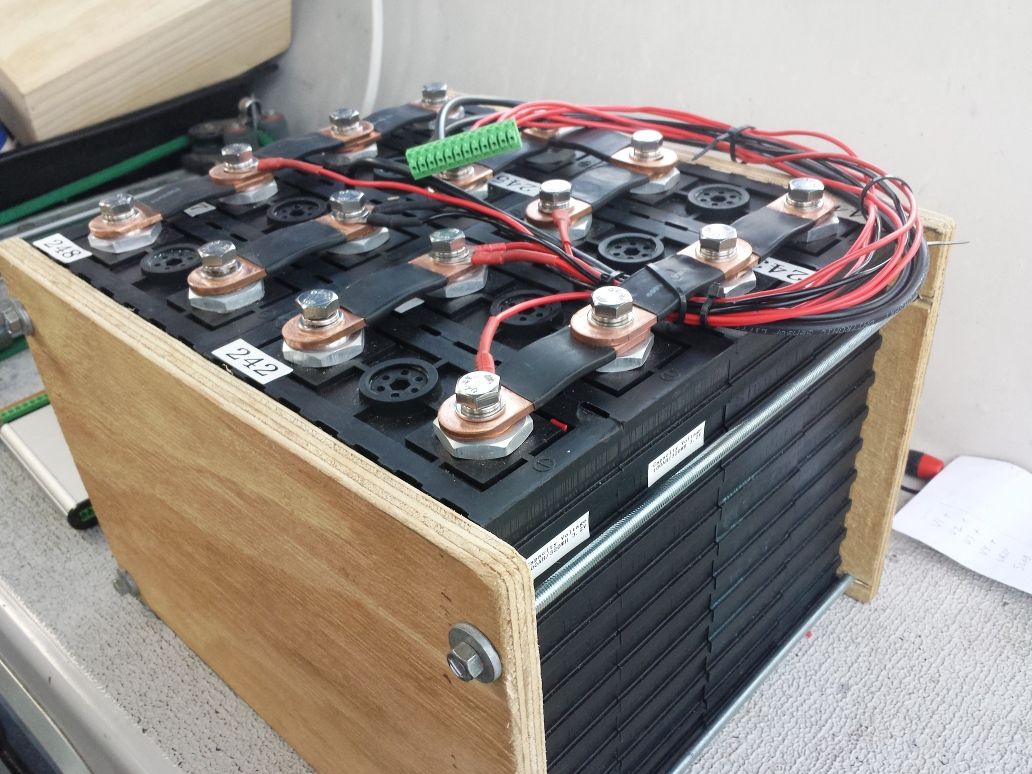
A 200Ah DIY lithium battery back for a yacht, balanced and instrumented for cell voltages and temperature. A standard 12-pin plug connector provides the interface to the battery protection module.
Cell clamping arrangements can be very simple and effective.
Buying cells and assembling the bank is not the beginning. Learning about lithium cells and understanding their properties and their risks is, before committing to building anything.
As it is an extensive topic in itself, the integration of a lithium battery on board is also dealt with separately.
Disclaimer
A good understanding of DC electrical systems is needed to build and commission a lithium battery installation. This article is aimed at guiding the process, but it is not a simple blind recipe for anyone to follow.
The information provided here is hopefully thorough and extensive. It reflects the knowledge I have accumulated building some of these systems. There is no guarantee that it will not change or grow over time. It is certainly not sufficient or intended to turn a novice into an electrical engineer either. You are welcome to use it to build a system, but at your own risk and responsibility.
How Much Capacity?
Generally speaking, a LiFePO4 bank will offer about twice the usable capacity of equivalent deep-cycle lead-acid cells in good condition, and much more when such lead-acid cells have deteriorated. This can provide a rough guideline when considering the purchase of lithium cells. In practice, it only suggests the maximum capacity that should be considered as a starting point: no more than 50% of the lead-acid capacity.
In the traditional lead-acid way of thinking, more capacity meant smaller cycles and longer life and a justification was found there: the situation is almost the exact opposite with Li-ion batteries
Many lithium banks installed on yachts nowadays are in fact not only much larger than they need to be, but also much larger than they should be.
The oversize bank approach can in fact deliver less value: there is nothing suggesting that a bank twice as large will last twice as long: it will more than likely just result in twice as many old buggered cells at the same point down the track if not earlier. The first consequence of installing an oversize battery bank, especially when sustained charging is involved as with solar panels, is that the bank remains at a higher state of charge much longer, if not most of the time. This is very detrimental to its ageing for reasons that were developed earlier. Lithium cells like cycling because it means they don’t spend any amount of time near full; alternatively, they can sit happily half-discharged, or even lower, for years.
Invest in energy efficiency or charging capacity, not in unnecessary storage
The bank needs to be large enough to provide the capacity needed between recharges, but beyond that, all what comes out needs to go back in and the size of the battery makes no difference there. Money is best invested in energy efficiency on board and charging capacity than storage.
The question therefore revolves around the cycle duration that must be accommodated. A yacht spending all its time in the tropics with considerable solar supply available on a daily basis doesn’t technically need to store much more than its overnight consumption, strictly speaking. The ability to accommodate a 2-day or 3-day cycle may be valuable however, but this calls for adapting the management of the battery to suit. Consumption can also be reduced in adverse conditions, extending cycle duration and this is a sensible way of looking at the matter, compared to calculating everything on maxima and worst-cases.
In practice, lithium banks of about 200Ah are easily capable of supporting yachts with an electric refrigeration system and auxiliary loads in the mid-latitudes and it is very difficult to present a valid case for installing more than 300-400Ah on a sensibly outfitted pleasure craft. Some, however, are fitted out and operated as if they were permanently tied to the power grid.
Some of the installations I built and commissioned included a provision for expansion by adding an extra set of cells later if needed, in order to alleviate the owner’s concerns. None of them were expanded afterwards
While a lithium battery bank can easily be expanded by adding more cells later if needed, unneeded capacity cannot be returned for a refund. Best long-term value is achieved when both the installed capacity and the management of the installation are correct and adequate.
Sourcing Cells
Manufacturers

Those are all common cells on the market today: the CALB SE-series in blue and CALB CA-series in grey (now identical other than for the casing). Sinopoly cells are black and Winston cells are yellow.
There are many manufacturers of LiFePO4 prismatic cells, mostly located in China, but the only well-known ones are those imported and available in the Western countries. Some smaller players like Hipower and Thundersky have disappeared. Some of the oldest names in the game today are Sinopoly, CALB (China Aviation Lithium Battery) and Winston, the latter having had a troubled history in recent years. Short of having a significant amount of time and access to a lab, it is very difficult to differentiate these products from a quality point of view.
Sinopoly and CALB operate their own research and development labs. CALB in particular has also established a very strong reputation for product quality control with each cell being measured and labelled with its actual capacity before being shipped. Yet, issues with CALB cells are not unknown to occur. Winston has been making reliable and long lasting cells for a very long time. In spite of being virtually unknown, Lishen also makes very good cells, which were selected by a large customer in Switzerland following lab tests, ahead of the better known brands.
While it is often possible to source unusually cheap cells with obscure brand names, such bargains might not represent long-term value. The ageing behaviour of the cells is extremely dependent on the quality of its manufacture and trade secrets associated with electrolyte composition and, in this regard, even the best known brands are not all equal.
Cell Sizes
Single 3.2V prismatic LiFePO4 cells can nowadays be obtained in huge capacity, as high as 10000Ah. Commonly available cells range between 40Ah and maybe 1000Ah. It should be pointed out that the larger sizes are intended for stationary applications where no accelerations, vibrations or shocks are ever experienced.
A sales manager at Sinopoly I was talking to was adamant about using 100Ah or 200Ah cells only for assembling marine battery banks, with 100Ah being preferred and 200Ah acceptable. Large cells simply don’t have the structural strength-to-weight ratio required to be taken to sea on board small crafts and would exhibit shortened life due to internal mechanical damage arising from on-going vessel motion. It is common sense: as a cell becomes larger, its internal weight increases much faster than the rigidity and surface area of the casing and the casing is all what holds the plates together in a prismatic cell.
Failures have been reported on vessels equipped with 700Ah cells following ocean passages: some cells were suddenly found to be losing charge inexplicably, rendering the battery bank completely unmanageable and the matter ended in a complete write-off. All big-brand commercial marine lithium battery packs on the market today are built from cells no larger than 200Ah.
While there certainly are examples of marine DIY systems that were built with large cells in series without issues, closer inspection usually also reveals a houseboat usage or infrequent good weather, sheltered waters sailing. In other words, the data point is null and void if the intent is sailing and designing upon the assumption that the boat won’t be going anywhere would be questionable.
Physical cell dimensions, space availability on board and interconnection topology are the other factors that influence the final choice of cell model. 200Ah cells are usually taller and require more “headroom”.
Condition Check
As much as possible, when sourcing cells from a local agent, I try to physically go there and check the cells as they come out of the crate. I normally decline buying cells that are no longer factory-packaged and may have been tampered with.
A set of brand new Sinopoly cells just out of the factory crate. All are reading within less than 1mV and their state of charge is just over 40%.
- I ask for cells from the same production batch, with consecutive serial numbers. Those should hopefully exhibit more consistent characteristics than randomly chosen cells.
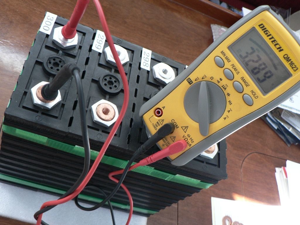
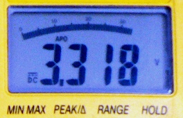
- All cell voltages must read below 3.300V. Pay attention to multimeter calibration there, there is a vast difference in terms of state of charge between 3.31V (over 75% SOC) and 3.29V (less than 45% SOC). This is to ensure that I am not getting cells that have been sitting around at a high SOC. This is not normally a problem with factory-shipped cells, but more caution applies with cells on the retail market.
- All cell voltages must be very closely matched. I like to see differences of 1mV or less, but sometimes accepted up to 2-3mV. At the SOC cells ship at, there is no justification for deviations in voltage, which could indicate a defective cell or prior tampering.
- Obviously, no cell must show unusual signs of physical use or prior connection. All cells are connected, charged and discharged at the factory following manufacturing, so there is no reason for any of them to appear any different, unless the cell is in fact second-hand.
If I place an order and cannot physically check the cells myself prior to purchase, I explicitly state all these conditions in writing with my order, so they become contractually binding if the order is filled. It can go a long way with eliminating the temptation to slip a “perfectly good” second-hand cell in a batch to get rid of it, knowing that returning it would be a major hassle for the buyer.
Warranty Conditions
Prior to purchase, I also get a warranty statement from the supplier. While warranty is usually limited to one year, this should cover any problems arising from major manufacturing issues.
Warranties on lithium battery cells are tricky, because the cells can easily be damaged through misuse and suppliers know that only too well. Chances of making a successful claim for a ruined bank or on an installation where cell-level protection didn’t exist would be near-zero (and rightly so), but it would be very difficult for a supplier to push back in the case of a single-cell failure on a properly engineered system.
In some countries, warranty clauses offered by vendors in general deliberately conflict with applicable consumer protection laws, so a one-year warranty doesn’t automatically mean that all bets are off after 12 months.
Pre-Balanced Packs
Some resellers sometimes offer “ready-to-go” balanced cell packs. While this could appear simpler than having to carry out cell balancing, the large amount of uncertainty existing around how the cells were balanced and treated prompts for extreme caution. These packs may have been exposed to excessive voltage and then left fully charged for extended periods of time, which makes them rather undesirable to own: the cells are already damaged.
The considerations about cell balancing further below contain all useful information required to validate the process used by the vendor, should one ever be tempted to go this way.
Cell Links
Consider sourcing cell links and stainless steel bolts in the same time as the cells. Cell manufacturers nearly always offer those. Use solid copper links in marine installations. Braided straps, such as earthing straps, even tinned, are not a good idea. They have a lesser cross-section than a solid conductor and will not age as well in the marine environment. They are bound to corrode and heat up severely one day.

Copper cell interconnection link. Those are readily available from battery manufacturers and resellers.
Alternatively, source 40 x 6mm (1 ½ x ¼’’) aluminium flat bar, cut it and drill it to suit. Sand the contact areas bright to remove the thin oxide skin. If using DIY links, consider insulating the sections between cell terminals using heat shrink tubing; it will greatly reduce the risks of causing an accidental short while working around the cells afterwards. Such home-made long links are particularly effective when dealing with blocks of cells in parallel and work out much cheaper than copper single links.
In all cases, the bolts must be long enough to thread deep into the cell terminals and be fitted with locking washers.
Transportation Considerations

Shipping crate for lithium cells
Shipping of lithium-ion batteries currently falls under very restrictive rules as they are classified as Dangerous Goods UN3480 Class 9. This determination can significantly increase freight costs and makes air freight essentially impossible today (2016).
Sea freight costs, on the other hand, are usually calculated on a minimum quantity of 1 cubic metre or 1 metric tonne (break bulk or LCL) and obtaining a good honest quotation for a small one-off shipment can be more than problematic at the best of times. Unless the order is large enough to approach 1 cubic metre, it is typically uneconomical to consider international sea freight, from China typically, because of the multitude of fixed processing fees and charges associated with landing and clearing the cargo.
The most practical pathway for sourcing small numbers of cells is often going through a company already importing such batteries for a purpose or another, such as electric vehicle conversions.
Battery Bank Topology
Once the system voltage and intended capacity have been established and a source/manufacturer has been identified for the cells, the topology of the bank can be determined according to cell size.
Electrical Interconnection
The principle is always the same: a 12V nominal system requires four identical blocks of 3.2V nominal cells, and a 24V installation requires eight. Each one of these blocks must offer the capacity sought after. Cells in the 100Ah to 200Ah range are relatively small building blocks and assembling larger banks requires creating parallel configurations.
Cell terminals and link plates must be sanded clean and bright prior to assembly: high resistance connections immediately result in hot spots at high current with the heat flowing straight into the cells. Connections should always be very tight for the same reasons.
In its simplest expression, a 12-volt lithium bank is built out of 4 cells connected in series; this is also the safest configuration. If more capacity is required, two main options are available in terms of architecture and interconnection schemes.
Parallel First, Then Series
The most common and simplest scheme is creating parallel blocks of cells of the required capacity, and then linking them in series to reach the voltage sought.
A 200Ah LiFePO4 bank can be assembled using four 200Ah cells connected in series, or four groups in series of two 100Ah cells in parallel. The first topology would be referred to as 4S (four in series, figure A below) and the second as 2P4S (two parallel, four times in series, figure B below).

Cell interconnection schemes for 12V systems. “A” represents a 4S configuration, “B” a 2P4S arrangement and “C” is the same, but fused.
The main advantage of these configurations is that they minimise the complexity of the protection required. It is also very easy to physically interconnect cells this way. The drawback of configuration B is that, should one cell fail by shorting internally, the others connected in parallel will discharge into it, potentially aggravating the situation.
This introduces a low, but additional, risk into the system that doesn’t exist with a pure series interconnection scheme as in figure A. Connecting cells in parallel to achieve large capacities is very commonly done however, even at industrial scale in stationary installations.
Fusing Individual Cells, or Block of Cells
A variant on the parallel blocks scheme of figure B is fusing some or all of the parallel cell links (figure C above). The challenge resides in sizing the fuses as small as possible, while still large enough to carry the normally expected currents without undue voltage drop and risk of blowing. We will note that in the case of configuration C, the fuses should never see much more than half of the bank total current. Fusing can’t prevent good cells from discharging into a faulty cell, it can only prevent them from heavily discharging into it, so the outcome and effectiveness of such schemes is uncertain.
On board marine vessels where loads such as inverter and windlass commonly draw in excess of 100A, the fusing requirements can be placed so high that they undermine the value of such arrangements for small banks.

In larger parallel interconnection schemes, such as this 3P4S configuration, individual fusing of the cells becomes increasingly important and provides a degree of fault tolerance.
The more cells connected in parallel, the higher the amount of energy available for heating a failed cell uncontrollably, but the smaller the individual cell currents. This can make individual cell fusing schemes more effective for larger installations. In the 3P4S configuration in figure D, each cell only contributes to one third of the total current and failure of a cell fuse doesn’t immediately compromise electrical supply to the vessel.
Large vessels can use banks comprising 8 to 10 cells in parallel in each block and then individual fusing can become very effective.
Parallel Banks
Deviating from parallel group topologies leads to building completely separate banks then connected in parallel. This requires a complete duplication of the protection/management system, but can be justified.

An active protection scheme with two independently managed 4S banks provides both redundancy and the highest degree of protection, but at the cost of duplicating the management system.
The approximate 200Ah physical cell size limit determines the capacity of each individually protected pack if no parallel discharge risk is the goal. This is the way commercial marine lithium offerings are usually constructed, as it minimises associated liabilities. A cell failure causes disconnection of the associated pack and the only energy involved is the one contained within the failing cell.
Summary
A simple 4S configuration (diagram A) offers both simplicity and maximum safety for a 12-volt nominal system. It allows building systems up to 200Ah.
The majority of the DIY lithium battery banks built to date have used the parallel+series configuration (figure B), occasionally with partial fusing as shown in diagram C. These topologies are not uncommon in large stationary installations either. At the time writing, I am not aware of any incidents arising from isolated cell failure within a bank on a marine DIY system. This doesn’t mean it couldn’t possibly happen.
Prospective owners of very large lithium battery banks should seriously consider using individual cell fusing, as shown in figure D, or going to multiple parallel banks as depicted in diagram E. The large number of cells increases the chances of seeing an isolated failure and the small size of the cell in relation with the bank suggests greater potential effects.
Production automotive battery packs are commonly made of very large numbers of small cells and typically fused as per figure D, and also broken up in separately managed and protected blocks. Those are usually connected in series afterwards to obtain high DC voltages, which is out of scope here.
Configuration E is arguably the best when it comes to minimising risks and maximising reliability while achieving a larger target capacity. It is more costly due to the duplication of the battery protection equipment and high-current disconnectors, but in the context of building a large lithium battery bank, the cost of protection should be seen as small.
Using larger cells in order to remain with a simple 4S configuration while achieving higher capacity would probably constitute a very dubious choice. Cells suffering internally from physical stresses and damage are much more likely to fail and short out than smaller, more robust cells simply connected in parallel.
Mechanical Installation
It was once thought prismatic cells could be operated in more or less any position as they do not really contain free liquid. Nowadays manufacturers are a lot more prescriptive with installation position. In most instances, the only acceptable position is upright, vent cap and terminals on top (Sinopoly, Winston). Sometimes it may be acceptable to mount them on edge, with the terminals on the side (CALB). This may vary not only between manufacturers, but also between cell models, so seeking specific guidance is a sensible step if an odd installation position is being considered.
When questioned, Sinopoly indicated that installing the cell in any other position than upright would cause some of the plates to run dry after a while, damaging it. Installing them flat on their side is out of the question in all cases.
The cells must be installed securely in such a way that no movement is possible in relation with each other, or it will stress the terminals and link plates. Prismatic cells should also be clamped together between compression plates as the application of a modest amount of pressure helps with preventing electrode delamination, even more so in the presence of shocks and vibrations as found on marine vessels. It also helps with preventing the internals of the cells from shifting in case of violent shock, which can lead to internal cell short-circuits. Clamping is a common warranty condition from manufacturers. Strapping the cells together is simply not good enough for that matter.
The bank must also be installed in such a way that it can’t shift and nothing can come and short-circuit the cell terminals. This can involve fitting a cover over the cells.
Location
Ambient Temperature Considerations
Lithium batteries age at an accelerated rate and degrade very quickly at high temperatures. For this reason, installing a bank in an engine compartment is completely out of the question. Ambient temperatures in the battery compartment should not exceed 30°C.
Conversely, exceedingly low temperatures can lead to temporarily reduced performance and capacity on discharge and cell degradation during charging. Marine house batteries are not normally operated at very high currents, but charging below 0°C is an issue that can arise for some vessels in some areas and needs to be prevented, especially at high currents.
Volume within the accommodation space and below the waterline is often the most suitable in terms of ambient temperature conditions for housing a lithium battery bank. Vessels operating in polar waters or facing harsh winters may require special dispositions ranging from heating the battery compartment to disabling charging.
Shocks and Accelerations
Prismatic cells are made of thin plates stacked together within a semi-rigid plastic housing. The stack itself hardly has any structural strength other than in compression. The edges of the plates are weak and can be prone to damage if the cells are exposed to violent impacts. Installing prismatic lithium cells into the bow section of a marine vessel is out of the question, no matter how tempting it may be to power a windlass. Wound cylindrical cells would be far for robust for that matter, but the battery assembly containing a large number of such small cells may not be. Shaking it loose over time could turn the battery into a fire risk.
A lithium battery bank should be installed aft of midships typically, in the most comfortable part of the vessel and the cells must be firmly clamped as discussed earlier. In the case of offshore vessels, the prospect of falling off a wave in heavy weather cannot be entirely excluded, hence the importance of selecting cells of modest size and weight for building marine battery banks.
Measuring Cell Voltages
 Before moving ahead with building a lithium battery bank and balancing cells, make sure you have access to a good quality, calibrated digital multimeter: cheap, junk-grade instruments are little else than voltage-inspired random number generators. It should read at least within 10mV of the true voltage in the 3 to 4 volts range with perfect repeatability and regardless of changes in ambient temperature.
Many of the “marinised” multimeters I have come across over the years were out by 0.1V or worse. If you happen to own one of those, complete with the proverbial bent probes or broken leads, do yourself a favour and place it carefully in a rubbish bin if you can’t give it away. While most multimeters can be adjusted internally, the cheap and nasty ones resist calibration attempts by drifting all over the place afterwards. The internal voltage reference they measure against is worthless and the measurement circuits are not temperature-compensated.
An instrument with a range of 4000 counts, rather than the more common 2000 counts found on low-end units, also means that it is capable of displaying differences down to a single millivolt between 3 and 4 volts.
Always measure cell voltages directly from the cell metallic terminals themselves, rather than the cell links or bolts. The readings are much more reliable. And keep your instrument in a sealed plastic freezer box, with the leads neatly folded and a spare battery: this also makes for more reliable readings on the long run!
Safe Handling
New cells come out of their crates fitted with insulator caps over their terminals to prevent accidental short-circuits. The extraordinary discharge current capability of lithium battery cells has been discussed already. Accident risks are very high while repeatedly connecting, disconnecting and re-arranging cells for balancing and building a battery bank. Keep the insulator caps on the cells terminals for as long as nothing is connected and insulate the tools used for making the connections. Most of the cells in the sizes suitable for building marine banks use M8 bolts and require a 13mm spanner or socket drive. Wrap this tool with insulating tape, or better, heat-shrink tubing, if it is going to be used in a sustained way, only leaving exposed metal at the working end. On the same token, cover the top of the cells you are not working on.
Shorting cells while working on their connections with a spanner could result in intense burns and the offending tool might weld itself to the terminals before failing “fuse-style”, sending molten metal flying around. Watching people working on cell connections is one thing that always makes me nervous.
Cell Balancing
Before a bank is physically assembled into place, the cells must be balanced. This step is absolutely critical, because if a cell becomes fully charged ahead of the others, its voltage and resistance increase very rapidly, the charging current collapses and the other cells can’t be charged any further.
When cells are manufactured, their actual capacity always deviates more or less from their intended nominal capacity; next the cells are cycled, tested and then left partly charged by the factory before shipping. There is every chance that cells even belonging to the same production batch won’t all share the exact same capacity and will not land in a state that would allow simply connecting them in series to obtain a balanced battery bank.

Trying to operate an unbalanced battery bank, such as when assembling new cells without precautions, results in problems both with charging and discharging. Here, cell 4 gets over-charged while the others are not yet full and cell 2 reaches an over-discharge condition while the others still have some capacity left.
At best, on a well-designed system, cell imbalance causes a reduction in available capacity and potentially some kind of alarming or even disconnect; on an unprotected, unmanaged system, it leads to cell destruction and can result in dangerous developments.
A bank can be top-balanced or bottom-balanced, but never both, because the cells never share the exact same capacity. The choice depends on the application and type of service.
Bottom Balancing
Bottom balancing is normally very undesirable for marine house banks as they hardly ever, if ever at all, get fully discharged and it creates most unwelcome difficulties with charging. Charging and managing bottom-balanced banks will not be developed here for these reasons.
For the sake of completeness and understanding only, some information is provided here about bottom balancing.

All cells are first discharged to a common low level prior to being assembled together. Charging results in one cell reaching full charge before the others, but deep discharge is no issue on the other hand.
The goal of bottom balancing is ensuring that all cells get to their low charge limit evenly together. Bottom balancing makes most sense in applications where deep discharge happens routinely, like in the case of electric vehicles that are driven almost to the point of running out of energy. For this reason, bottom balancing was introduced (and rather successfully at that) by people building DIY electric cars, such as Jack Rickard at EVTV; until then, not only they lost a lot of cells, but some also managed to incinerate a few vehicles.
In order to bottom-balance a set of cells, each cell must be discharged down to a voltage that is at or below what the low voltage cut-off setting will be. Typically, this would mean a value of about 2.5V. The best and quickest way to achieve this is wiring all the cells in parallel and discharging them through an automatic low voltage disconnect device. Power resistors or light bulbs are all usable loads for discharging.
One should remember that if the cells are accidentally over-discharged in this process, they will be destroyed. Over-discharge means reaching below 2.0V for LiFePO4 chemistry.
Once all cells are down to the same low stabilised voltage, the bank can be assembled and charged.
A bank that has been bottom-balanced will invariably go out of balance at the end of the charge. This is unavoidable. The voltage of the smallest cell will peak up ahead of the others and throttle the charging current. If, at this point, charging is not immediately discontinued, this cell will quickly get damaged through over-charging.
Top Balancing
The goal of top balancing is ensuring all cells get full together at the end of the charge instead. Top balancing is almost the rule for all applications where very deep discharge essentially never happens, and this precisely includes marine house banks. Top balancing makes the task of recharging the bank more straightforward, because the total battery voltage is distributed quite evenly across the cells near the top end.
At the bottom end, one cell will invariably drop out first and if the bank is discharged beyond this point and the voltage of the weakest cell falls below 2.0V, it will be destroyed by over-discharge.

All cells are fully charged before being assembled together. A deep discharge can cause the smallest cell to “hit the bottom”, but charging is normally no issue and all cells can easily be stopped short of over-charging.
Top balancing is by far the most common process used for building a lithium battery bank, because cell imbalance issues at the low end normally never become apparent, on the basis that cycling that deep doesn’t normally happen; at this point, the bank hardly has any stored energy left and cutting it out becomes a simple and logical response.
In order to top balance the cells, they need to be charged in parallel until well into the upper “knee” region of the voltage curve, where small differences in state of charge become very visible in terms of cell voltage.
How the cells actually get charged is irrelevant as long as they are kept within their voltage limits throughout. Unlike often stated, there is no point pushing the cells to voltages far exceeding 3.6V to balance them. It is just a good way of starting with electrochemical damage and achieve absolutely nothing else.
We are going to present two options for top-balancing a set of cells.
Method 1: Charging and Balancing Cells Using a Regulated Power Supply Unit
There are a few options available for first charging and balancing the cells. Using a regulated bench top power supply unit (PSU) is the commonly promoted approach and also the least practical and accessible for a one-off job on board – which is often the context in place when building a DIY system on an ocean cruising yacht. This process is very slow, inefficient and requires a regulated power supply unit and mains power for several days.
In some cases these constraints don’t apply or this method can be combined with the second method to “finish off” the cells, so the process is explained below, but you should prefer the second method described.
Never use a common battery charger: its output is unregulated and, even if it is able to hold without overloading and tripping, it cannot limit the voltage as the cells charge up. The guaranteed outcome will be a totally destroyed set of cells at best, or a fire. Don’t imagine for a second that you will be able to “see it coming” and prevent it. The voltage seems to remain constant forever and then rapidly rises without any warning.
You need an adjustable, regulated power supply unit to follow this process.

Parallel charging and top-balancing cells using a regulated power supply unit (PSU).
Voltage regulation is essential to ensure the target voltage cannot be exceeded.
First of all, power the PSU before connecting anything to it and never interrupt the mains for as long as there are batteries connected to it. Some PSUs are not well protected against reverse current flow and not intended for use with large capacitive loads!
If possible at all, use a PSU that is explicitly suitable to charge a battery; in doubt, use great caution as a mishap can easily damage it. If smoke escapes from it, you will never get it back in.
- With the output disconnected, set the voltage regulation limit at 3.40-3.45V and preset the current limit (if any) to a value that won’t overload the PSU. Refer to the manual as required. In doubt, always start with a low current limit and never exceed 80% of the rated output.
- With all the cells wired in parallel, connect the PSU, bulk charge and absorb until no current flows any more. The voltage will stay around 3.3V for a very long time before starting to rise. Charging this way can take several days. This will near-fully charge the cells without stressing them unduly, but don’t hold them at that voltage indefinitely. Keep checking up on them at least a couple of times each day. Briefly disconnect the cells and recheck the voltage limit setting on the PSU: better safe than sorry. Avoid charging the cells individually, or in batches; the whole process would take just as long, but would also result in some fully charged cells lying around for several days.
- Once the voltage has reached the PSU output regulation limit and there is no apparent charging current any more, disconnect the cells from the PSU and increase the output voltage regulation limit to 3.60V.
- Then, while standing by only, reconnect the cells and allow the voltage to rise up to 3.60V and stabilise for a few minutes; this normally takes little time and additional current, provided the cells were fully absorbed at the lower voltage. Whether you target 3.60V, 3.65V or even 3.70V is of no consequence or interest if you are actively monitoring the process, because these values are often reached seconds apart only.
- Disconnect the PSU from the cells again and wait. The cells should hold above 3.50V for at least 30 minutes. If not, bring them up again and hold them for a little longer until they do. At 3.60V, you may need to insist a little more than if using 3.65 or 3.70 volts; that’s all.
As with all unattended charging of lithium batteries, some very careful thoughts must be given to the potential consequences of a failure somewhere
Using a regulated PSU, a failure of the unit – no matter how unlikely – cannot be entirely excluded and there is no other line of defense in place. Hopefully, it would just trip, but if it didn’t, it could lead to a battery fire. Someone could also come past and interfere with the equipment during charging with the same outcome.
Method 2: Charging and Balancing Cells on Board
After going about charging and balancing cells in a few different ways, I devised this method. It has since become the solution of choice for one-off lithium battery projects, because it is much more efficient and doesn’t require equipment that is not already available on board.
The idea is rapidly bulk-charging the cells using the boat’s engine and alternator and then addressing the balancing part separately.
I also consider it as potentially safer, because it is short enough to be fully supervised.
While the process usually takes a couple of hours only, it requires unfailing vigilance. This is only feasible because the time frame is short. If you have access to a regulated PSU, proceed up to step 6 and then consider finishing using the first method.
- Assemble the lithium cells in the final topology the bank will be using and bolt the on-board battery cables to it, as if performing a direct replacement. In some instances, this requires shifting the old lead-acid cells out of the way first. It is important that a heavy-duty connection is made between the lithium battery and the alternator.
- Start the engine normally, run at idle for a couple of minutes and then rev it up. This will immediately result in a high alternator output. Check that the B+ (output) post of the alternator doesn’t heat up; this would indicate a bad or dirty connection and easily cause the alternator to fail. Also check all the cell connections for any temperature rise. All electrical connections should remain cold. Next, be mindful of alternator temperature. It is advisable to keep the charging current no higher than 80% of the alternator rating. Keep the engine compartment open if necessary and reduce engine revs if required. Twin-engine vessels like catamarans can (and usually should) charge with both engines. Keep a voltmeter connected directly to the bank.
- Make a cup of tea and watch the voltage. New cells normally ship at 40-50% SOC, so a simple initial calculation can provide an idea of charging time. It is normally a matter of 1-2 hours. After remaining stagnant around 13.40V for a long time, the voltage will eventually start to rise. Periodically measure the individual cell voltages to ensure they don’t diverge abnormally and all remain below 3.60V. If this becomes tedious or distraction sets in, shut the engine down, disconnect the bank and carry on later. Should any cell reach 3.60V prematurely or, conversely, clearly lag behind the others, it is an indication that the cells weren’t in a consistent state of charge at all when sourced. This should be seen as a warning flag about a potential quality issue, like a significant difference in self-discharge rate or internal resistance.
- The voltage will eventually reach the alternator regulation limit, normally 14.20-14.40V. If this was set higher (through the use of an external regulator typically), don’t allow it to exceed 14.40V. At this point, the individual cell voltages should still appear very even, because the cells were charged at a fairly high rate and are not full yet; only the bulk charge has completed.
- From this point onwards, differences in cell voltages are going to start appearing. Only individual cell voltages matter. Identify the highest cell(s) and gradually reduce engine revs, so none exceed 3.60V. Keep reducing revs until down to idle, then shut the engine down. On a twin engine vessel, cut back and shut down one engine first. After about 30 minutes, most of the absorption phase is complete and the unbalanced bank cannot be charged any further without experiencing excessive cell voltage issues.
- Disconnect and break up the bank, and now connect all the cells in parallel. If a cell is reading more than 0.1V higher or lower than the “pack”, parallel it with a small jumper cable at first to prevent any large current inrush, and connect it with the heavy link plate once the difference has subsided.
- Once all the cells are wired in parallel, they need to be properly topped up and balanced.
- If significant solar capacity is available, take the solar feed from the panels (before any charge controller!) and connect it directly to the lithium bank. Solar panels are current sources and don’t care about their output voltage. They will contribute about the same current at any voltage.
- Alternatively, bridge from the old lead-acid batteries (or a basic battery charger) using a few metres of electrical wire (not cable!). The wire acts as a resistor, dropping the voltage and limiting the current. Depending on the length available, 2.5mm2 (12AWG) or 4.0mm2 (10AWG) are normally suitable choices. If there are 6V batteries available, bridge from 6V, otherwise bridge from 12V. The wire will heat up as a result of the voltage drop. If it gets too hot, stop and use a longer or smaller wire. Use caution and common sense.
- Bring all the cells up to 3.60-3.65V, disconnect and keep recharging this way until they all hold above 3.50V for at least 30 minutes. They are then full and balanced. Don’t leave the circuit closed and unattended under any circumstances; it would very quickly destroy all the cells.
This method is many times faster than parallel charging throughout, but more labour intensive and requires continued attention. It is only feasible because maintaining complete focus for a period of 2 to 3 hours is not unreasonable. If you are negligent or over-confident and leave the process unattended for any amount of time, you will likely damage or even lose the cells completely.
Additional Considerations
A few additional notes regarding cell balancing:
- Refrain from pushing cell voltages above 3.60-3.65V. You can trade a little more time for less voltage and achieve the same without stressing the cells. Balancing cells is not a hazardous process involving excessive voltages, infrared temperature guns and a fire extinguisher in standby: it is just a one-off, full parallel charge within normal voltage limits.
- Use heavy link plates or substantial cabling in relation with the charging current to connect the cells in parallel, and preferably feed “in the middle”. The objective is keeping all the cells at the exact same voltage while they are charging. If the cell interconnections are dropping voltage, the cells away from the feed point will see a reduced charging voltage, at least until near the end of the charge.
- Don’t waste time leaving cells sitting around connected in parallel. They don’t balance or equalise unless they are being charged in parallel at the end. I have specifically tested that. There is not enough voltage difference to keep driving current between cells until they balance out.
Discharging Afterwards
Once the cells have been charged and balanced as described above, they should be assembled into their final topology immediately and the bank must be discharged at least down to the equivalent of 3.325V/cell: that is 13.3V for a 12V nominal system, or 26.6V for a 24V nominal system. Don’t allow the cells to sit around at 100% SOC after balancing! If the balanced pack is going to remain out of service for some time, it must be further discharged until it doesn’t read more than 13.15V (or 26.3V) after balancing.
There are dealers who offer – for a premium – “pre-balanced” lithium battery packs that were fully charged in parallel, interconnected and then stored on a shelf… buying those often equates to paying more money for deteriorated cells, because the packs are typically never discharged again once charged and balanced. They may also have been exposed to excessive voltages for long periods while being charged.
This why I only ever source factory-packaged cells.
Next Steps
The tasks described in this article lead to building a top-balanced battery bank of a given capacity. Before anything can be done with it, the cells must be protected from voltage excursions outside their safe operating range and automated measures must be put into place to take action if any abnormal conditions, whether it is voltage or heat, are detected.
The electrical system on board must also be altered in order to separate charging sources from loads, so both can be isolated independently at any time to protect the battery if necessary.
Last but not least, charging sources must be made compatible for charging lithium batteries in terms of voltage and operation. This is not always possible and some devices may need to be replaced.
Hi,
Concerning Method No. 2 for balancing the cells, is there a problem with using the on-board battery charger such as a Victron Multiplus for the bulk charge in lieu of the alternator? Is there a way to program the Victron to do the top up as well?
Thanks,
Julian
Julian,
You can certainly charge the cells using a mains-powered charger, from the charger point of view, it is no different than charging any battery. However… going about it this way could take a lot longer than with an alternator, unless you have a high-capacity charger. You can’t leave this process unattended and if it is going to take many hours, you almost certainly will… this is the problem.
In order to top up, you would be connecting the charger to a very low-impedance, low voltage load (the cells in parallel at ~3.50V). How the charger will take it is an open question. A good charger should limit its output current and do the job. Another one might overload and trip or even burn out. If you also use a long wire as a resistor, then you should definitely be able to do it this way.
I don’t go into the details pertaining to specific equipment, manufacturers can answer questions about their products. Here I would just like to point out that an inverter/charger has no place in a dual DC bus lithium system, because it acts both as a load and a source and there is nowhere to connect such a device without creating an issue. You need to make a choice between the charger or the inverter.
Best regards,
Eric
Good point Sir! Thanks.
I have the same problem, Julian is dealing with.
Just designing two busses for the DC side, but also want to use a inverter/charger. Not for initial charge, but for usage afterwards.
Is there a wise way to configure the system, that I can make the inverter/charger work both ways?
Got the same Victron Quattro, which can be programmed for charging LiFePo via Landsupply and Generator, but it is also a good and strong inverter…
Thanks and best regards,
Ralf
Hello Ralf,
I had the opportunity to give further thoughts to this problem with combined inverter/chargers last year and I designed a solution using two low voltage drop (FET-based) battery isolators. A large one from the load bus to the inverter charger DC terminals and a smaller one from there to the charge bus. Just link the outputs together to use them as single large ideal diodes. It adds cost, but it enforces the isolation of the DC buses.
Kind regards,
Eric
Hey Eric,
thanks for the immediate reply and Your further thoughts solution!
Sounds like a perfect way to achieve both!
Do You by chance have a sketch for this, which I can forward to my electricians (unfortunately I‘m none), or some suggestions for dimensions? Or a place, where I can find further information for this?
Really appreciate Your help!!
Best regards
Ralf
Hello Ralf,
For now, I will e-mail you a little sketch, but there is not much to it. I will consider adding a diagram in the other article about electrical design, here is not the right place.
You need to know the maximum current the inverter can draw on the DC supply to dimension one isolator and the other only needs to be able to carry the current the charger can deliver to the battery (usually quite a lot smaller).
Kind regards,
Eric
Good morning Eric,
thanks again very much for your effort to help me in this topic!
The inverter/charger (a victron quattro) produces 5000W (12V system) and can charge up to 220A. It can be programmed to a lithium charge profile.
Unfortunately didn´t receive the sketch yet.
Kind regards,
Ralf
Ralf,
The reason is that looking after people who post comments is not the only thing I have to do these days and, while I always try to reply within 24 hours as much as possible, extras can take a few days.
Drawing 5kVA from a 12V nominal supply is borderline stupid as the DC current gets in the 400-500A range and, in these conditions, the option I was outlining is probably out just because of equipment availability reasons. Resistive losses go up with the square of the current.
Inverter and charger need to be separate and the charger must be controlled by the BMS to terminate correctly. There is no such thing a “lithium profile” with lead-acid chargers.
Eric
Very complete an helpful article, would you know why only Winston battery can tolerate -45C and Sinopoly and CALB only go down to -20C.
I need a battery bank that can be left in a not heated building during winter months ( unplug / Storage mode ) that temperature could go down to -40C.
Do you have any suggestions, what do you think of LTO battery?
Hello Charles,
Experiments have been conducted freezing LiFePO4 down to -70degC or so from memory and they eventually become completely inert no matter what their state of charge is. They returned to normal with full capacity once back at standard temperatures.
It pays to keep in mind that CALB and Sinopoly have historically been more conservative in their specifications than Winston. The other aspect is that when Thundersky was bought by Sinopoly some years ago, somehow they didn’t get the patent for the modified yttrium chemistry of the Thundersky cell. This went to (belonged to?) Winston. This modified chemistry has been touted to be superior in cold temperatures and Winston advertises not only storage but also charge and discharge down to -45degC. I have never seen any data supporting these claims however and so the question is whether we should believe them… Back in 2007, Thundersky was giving no storage temperature limits, but specified operation between -25degC and… +75degC!! CALB is happy with storage and discharge down to -20degC. Sinopoly suggests discharge down to -20degC as well, but storage down to -10degC. This is from datasheets I have had on file for some time by the way.
I don’t know what the rationale is regarding the lower storage temperature limit. Maybe mechanical stresses with differences in the shrinkage rates between materials or freezing point of the electrolyte (but I wouldn’t expect the yttrium to make much difference then) or very possibly just a lack of data. Very low temperature storage is not something you would normally go to great lengths to characterise… You could write to all three and ask them, Chinese companies are normally quite good with replying.
Personally, short of CALB or Sinopoly coming up with a constructed explanation as to why not to keep cells stored at the temperatures you are considering, I would be tempted to just do it, especially if the investment wasn’t huge.
Building a LTO battery is something that crossed my mind, but I can’t really see a justification for the much higher cost considering that, after some 10 years now, we still don’t really know how long a LiFePO4 bank can last in a good installation.
Best regards,
Eric
I am about to place an order for LiFePO4 batteries encased in aluminum and am trying to figure out the best way to build the bunk. There will be 32 cells in a 2P16S configuration for a 48v motor. Should the cells still be packed in a compressed (clamped) configuration like the plastic cased cells (CALB, etc)? If not, should I then design the bunk to allow air circulation around the individual cells to better facilitate cooling?
Great article, btw. Especially the tips on placing the order.
Hello Jon,
Cells in aluminium casings are less prone to delamination over time, but you are going to need to secure them anyway, so you can just as well clamp them.
Cooling is very much a question related to the amount of current you are going to run. In my experience, it is not relevant at C-rates of up at least 1.0, and definitely irrelevant at 0.7C. I suspect that your average discharge rates will be much lower, so you shouldn’t need to worry about air flow.
Note that as cells age, their internal resistance also increases and they start to run a little warmer than when fresh and new, but we are talking about a few degrees only, at the most. Unless your ambient temperatures are going to be high already, it hardly matters.
All the best with your project,
Eric
Thank you. I anticipate sustained discharge rate of .5C for about an hour. Longer times than that would be at even lower, any higher rates of discharge would be for shorter periods. 1C would definitely be less than a minute at a time. (Motor = 20 kWh, with battery capacity a little bit higher, depending on the cells I end up ordering).
I plan on really babying these cells BS keeping them out of the knees. I hope not to age them prematurely.
The cell temps will be monitored by the BMS via thermistors and when in use. I know internal resistance affects temperatures and is a function of the quality of manufacturing which is always a gamble with Chinese manufacturing (despite the assurances of the U.S. distributor). Still, clamping the cells makes the bunk design challenge so much easier and takes up less space in the end.
Thanks again for sharing your wisdom.
Jon,
You must mean 20kW for the motor. kWh is an energy unit, not power. If your average discharge rate exceeds 0.3C, then it might suggest that the battery capacity is on the low side on the basis that the recommended charge/discharge rate for long life is typically 0.3C with LFP. However, it also depends on how much you use the system.
I would not recommend “dropping them underneath the bunk because it is more convenient” on the basis that any movement will also stress the cell connections and I stopped counting the failures I have seen in LFP systems due to overheating at bad connections a long time ago.
“Keeping them out of the knees” is popular internet garbage. If you don’t charge LFP cells correctly and properly at least from time to time, they develop problems with early voltage rise or, in other words, the “knee” you are trying to avoid moves back against you and the useable capacity shrinks until you have too little left to operate. It is caused by a memory effect that develops and strengthens over many cycles when they don’t get returned to full. Charging them properly requires voltage and absorption time until the residual current condition is met.
When it comes to the low end of the curve, there is no drawback in using the available capacity as long as the bottom voltage is not breached.
Bashing the Chinese manufacturers is also quite popular, except that it has no foundation. The main players seem to consistently deliver good cells with very few issues and I would be far more concerned with what happens afterwards with the retailers.
All the best,
Eric
Hi Eric, you’ve written a great series!
I’m currently working on a 3p8s pack using CALB 100Ah FI cells. I want to implement the circuit you describe in figure D: individual cell fusing. In CAD, I found that for these CALB cells, ANL fuses seem to fit perfectly, physically at least. What do you think of this approach, and would you recommend something else?
Hello Antoine,
Fusing the cells is always conceptually attractive and ANL fuses can indeed replace cell links quite simply in some cases, but it can be difficult to do it in a way that is actually effective, unless:
1/ The parallel blocks each contain a lot of cells; and/or
2/ The currents in the installation are always small in relation with the capacity of the individual cells
These conditions are rarely met when using relatively large prismatic cells in small installations. In your case, using a 3P scheme, each fuse must be able to hold a current of Imax / 3. This can be too high to effectively protect an individual cell, unless Imax is very small.
The other aspect to keep in mind is that there is no reason for a cell to start failing in short-circuit uniformly. It is more likely that it would fail by developing a hot spot and then the failure would progress from there. There is no guarantee that the fuse would be challenged before a hot spot could reach ignition temperature for example. I have never seen or heard of such a cell fuse blowing when used with a few prismatic cells in parallel only.
In the case of a gradually developing fault within a cell, the first sign of trouble, long before any noticeable heat is generated, is usually cell balance issues (i.e. overvoltage in charging) with most or all the healthy blocks and the installation becomes inoperable, so you tend to get a warning.
All this suggests that if you are really serious and concerned about individual cell failures within small parallel blocks, you don’t create such blocks in the first place and operate 3 independently managed 8S strings in parallel instead, because this is always the safest configuration.
In practice, experience shows that parallel blocks rarely give trouble and, when they do, cell balance issues arise long before anything else, because it only takes a very small amount of abnormal self-discharge in one cell to upset the pack. As a result, and because it is also much simpler and cheaper, a lot of people choose to operate parallel cells when seeking larger capacity. In non-stationary applications, smaller parallel cells (up to 200Ah typically) are always much better than single larger cells, because they are a lot less likely to fail from mechanical stresses.
Best regards,
Eric
Hi Eric,
Thanks a lot for your response! I appreciate that you took the time to write such a detailed answer. And indeed I bought these 100Ah cells (instead of larger ones) based on your article and mentions of mechanical stresses.
I think I will proceed without the ANL fuses, with the 3p8s configuration. I’ll follow the other recommendations you made, I just need to re-read each article another time! It’s dense with a lot of good information! For the BMS part, I acquired an Orion Jr BMS, which seems to be fulfilling the requirements that you mentioned. It was also easier to procure from California than other models.
For marine applications it seems there is lots of opportunity for charging such as solar, alternators when motoring, shore power.
This seems like to would result in the bank spending a lot of time at 100% SOC while you indicate keeping the bank at high SOC for long durations is not good for the bank or is your idea of long durations at high SOC more in the weeks/months range rather than say a day?
Can you clarify?
I suppose when the boat is not in use for longer periods such as several weeks the bank should be drained a bit and then disconnected?
Paul,
This is one of the dilemma when trying to use lithium batteries in standby applications. They are not a good fit to create reserve capacity for occasional events. Unless you are living aboard and cycling them significantly, there is generally no value in departing from lead-acid, on the contrary.
This idea of “keeping the battery full” that originates from the sulphation problems of lead-acid chemistry, but also aligns well with maximising reserve capacity, has to be abandoned completely. If you are not using a lithium battery, it should be stored in a significantly discharged state and then it offers very little reserve capacity.
Not keeping the battery full and not recharging the battery unnecessarily is another aspect of battery management for long term performance.
If you leave a boat connected to shore power with lithium batteries, the cells should not see any charging and this suggests keeping the system voltage constant at a low level like 12.8V or less for a 12V installation. More and more chargers can be configured to operate in a power supply mode now for this reason.
Best regards,
Eric
One thing I’m still confused about is why do the cell voltages rise rapidly with an unregulated PSU such as a battery charger?
If I charge my 12V pre balanced pack with 14.6V will each cell eventually go beyond 3.65V? If so I don’t understand why.
Are there easy ways to spot noticeable miss matched IR & AH in the cells once built into a 12V pack?
The cell voltages rise very quickly at the end because the battery runs out of lithium ions to displace (which is the reaction that happens at the “normal” charging voltages) and then the electro-chemical potential moves up towards the next reaction level where the electrolyte is decomposed around 4.2V. It is not a problem of internal resistance, it is not an ohmic effect, even though it looks a bit like it. It is asymmetric, it only happens with current flowing in and not in discharge at the same charge level.
If you charge a perfectly balanced 4S pack at a filtered and regulated 14.6V, all cells will reach 3.65V. If there is any imbalance, the sum of the cell voltages will remain 14.6V, but the maximum individual cell voltage could become much higher than 3.65V.
If the charge voltage is not properly regulated, then the cell voltages could become anything with almost zero current flowing.
Kind regards,
Eric
30 deg C max ambient temperature is not realistic on a boat…is it?
Average ocean temperatures peak around 28degC, so a bank installed below the waterline should be able to stay reasonably close to that in the context of ocean cruising. The hottest I ever saw the sea was 32degC close to the surface in the doldrums of the Atlantic and I wasn’t there for very long. I also had sea temperatures of 1degC in the Antarctic and excess heat was never a problem then.
Eric, thanks for your detailed explanations. I have a largish catamaran that I’m replacing the 1000a/h agm battery. I chose CA100 cells with a max discharge of 200amps (3 minutes) in an 8P4S config to deliver 800 a/h’s. I have a single 4 cell active bms. Costs aside, would you suggest no fuses, or fusing individual cells, or a block of cells, or splitting into 2 x 4P4S in parallel with/without fuses and a 2nd bms?
Stephen,
It is a question of personal choice as each option delivers a slightly different outcome in terms of resilience and possible failure modes.
It is very problematic to effectively fuse parallel cells when using small numbers of cells, unless the prospective individual cell currents are very low in comparison with the capacity of the cells, i.e. small fuses can be used.
I have never seen or heard of such a cell fuse blowing, probably because they are almost invariably too big and cells don’t normally fail into a sudden short.
A dual-bank system, like 2 x 4P4S in your case, with two BMS provides full redundancy. I generally don’t favour the full redundancy / two-of-everything approach on board cruising vessels because of the increase in complexity (and often weight) coming with it; very simple workarounds are often available in the highly unlikely situation that something would actually happen unexpectedly. In the case of a house bank, a severe failure can be mitigated by disconnecting it and bridging the system to the engine starting batteries.
Best regards,
Eric
Space constraints may suggest that “Flat on their Sides” (FotS) is preferable in some cases. However, in this article, it is stated:
“Installing them flat on their side is out of the question in all cases.”
Can references be provided to back this statement? Does capillary action not keep the electrolyte distributed sufficiently homogeneously? Are there obvious phenomena in either manufacturing or normal usage that give rise to the presence or development of (non-vented) gas, (slowly) rising by buoyancy, subsequently de-wetting/insulating/disconnecting parts of the electrode “sheets”? What would be the influence of a permanent moderate clamping pressure that is homogeneously applied across a FotS cell outer surface?
Thinking out loud: Would installing cylindrical (e.g. 18650) cells on their side then also be out of the question? Assume similar electrode- and electrolyte material, parasitic reactions, and gravity. The wound structure would seem to provide a more stable internal geometry, possibly delaying gas collection at the top w.r.t. FotS prismatic cells, assuming tight manufacturing tolerances during cell assembly. Yet, with the passage of time, they too may suffer deterioration similar to FotS prismatic cells.
Johan,
I queried the matter directly both with Sinopoly and CALB and the answer was categoric each time: installing the cells flat on their sides would cause the upper plates to run dry.
There is no free liquid electrolyte in LFP cells – all of it is absorbed – and there are voids in the top of a prismatic cell where the connections are made to the terminals. The amount of electrolyte present is not sufficient to fill these voids while also keeping all the plates wet. This problem doesn’t exist in small wound cylindrical cells.
I know that it may be tempting to install prismatic cells on their sides in some cases for geometric reasons and early EV installations even showed some mounted this way, but it is out of the question unless the manufacturer specifically indicates that it can be done for a given model of cell.
Best regards,
Eric
Eric,
I am having trouble sourcing the link busbars for my cells. I purchase 16 100Ah cells and am going to place them in 4P4S configuration. I have a total of 16 link busbars but need more to accomplish the goal.
I see that you recommend solid copper or aluminum. What about concerns in flexing from the cells and stress placed on the cell terminals?
I will be using 1/4″ aluminum plate and threaded rod to create a compression case for the cells but I still wonder about movement. Even a small amount of movement between cells would put stress on the cell terminals if the busbars were rigid.
I have 1/8″ x 3/4″ solid copper bar and am considering using 2 of these stacked on top of each other to make a 1/4″ x 3/4″ busbar. Thoughts about this approach?
Thank you
Jason,
LFP cells in our type of application behave like cold, inert blocks of plastic. If they don’t, it means that some serious damage is being done to them internally and stress on the terminals would be the least of your worries then.
The resistivity (ρ) of copper at ambient temperature is typically given as 1.72 x 10^-8 Ωm. The resistance R of a conductor can be obtained by calculating R = ρ x L / A where L is the length of the conductor and A is the cross-sectional area.
So, for a single 1/8” x 3/4” copper bar 1” long, we would get R = 1.72 x 10^-8 x 0.0254 / (3/4 x 1/8 x 0.0254^2) = 7 μΩ. As you can see, this value is ridiculously low and there would be no point in stacking two bars. In fact, the second one might not even contribute much because the resistance of the connection between the two could easily be much higher.
If you instead used a piece of marine-grade 6063-T5 aluminium flat bar, the resistivity of the material would be about 3.2 x 10^-8 Ωm (ASM Specialty Handbook Aluminum and Aluminum Alloys), so not quite twice that of copper. This suggests that 1/4” aluminium flat bar would be a better choice for making the busbars in general, harder, stronger and cheaper than copper.
Best regards,
Eric
Eric,
Thank you for your response. I hear that there is little concern about movement between cells so solid bar should not be an issue.
I am a little bit confused about your statement that the aluminum flat bar would be the better choice. Is this based only on the facts that it is harder, stronger, and cheaper than copper? Since copper has a lower resistance, if they were equal in price, or in my case I already have 1/8″ x 3/4″ copper, wouldn’t the copper be better? The strength and hardness do not seem like that are very important in this application. Perhaps I am missing something here.
My concern with using just the single 1/8″ x 3/4″ comes from the rated ampacity of such a bar. According to https://www.copper.org/applications/electrical/busbar/busbar_ampacities.html the cross sectional area is 119.4cm and a rated capacity of 215 amps. I have a 400Ah bank with the potential to pull up to >233 amps at any one time based on my 2800 watt inverter as well as the various DC house circuits, I would think that a higher ampacity should be called for.
I seriously doubt that I will ever even come close to that level of output but I would prefer to error on the side of caution when sizing wiring and busbars.
Jason,
Copper is quite soft and 3mm if a fairly thin flat bar, which needs to be clamped down very well at each terminal with a stainless steel bolt and locking washer. You will no doubt use the copper because you already have it, but a 1/4”-thick aluminium flat bar is more robust. Copper makes a better conductor for the same cross-section, but doubling the cross-section and using aluminium is no issue here. A lot of power distribution cables are aluminium for the same reasons.
I have issues with your source above on the basis that the cross-sectional area of a 1/8” x 3/4” bar is 3mm x 19mm = 57mm2. “119.4cm” is a length and it is non-sensical in this context. Based on the resistivity R = 7μΩ/inch we calculated earlier, at I = 250A the busbars would dissipate P = R x I^2 = 0.44W/inch. If you were going to sustain this kind of current for long periods, a case could be made on the basis that you don’t want them to gradually warm up the cells over time, but it is not going to make any difference whatsoever if you occasionally peak at 250A for short periods. When it comes to a busbar actually “failing”, even a hit at a few thousands of amps wouldn’t be enough to achieve that and it would blow the protection fuse long before the bars would have a chance to heat up.
If you made your busbars out of aluminium, you would not be restricted to a narrow width of 3/4” only and they would in fact have a much bigger cross-section and be able to handle more current for less temperature rise.
If you stack your copper strips, you will need to sand them bright at the connection points and be very careful to achieve good conduction through the joint and it might still not last over time in a marine environment.
I once saw a lithium bank that was exhibiting unmanageable cell balance problems just because one cell in one parallel block wasn’t contributing properly: excessive resistance in the connection, and yet it was bolted tight. It came right after sanding all the faces bright and reassembling and this is why I would choose a solid bar rather than trying to use small copper strips. 3/4” is barely wide enough to be attached with M8 bolts.
Best regards,
Eric
Eric,
All great thoughts.
I hadn’t really thought about the cross sectional area until you pointed this out. You are correct that the area they give makes no logical sense. Their current capacity still seems to hold against others with similar charts however. https://bralpowerassociate.blogspot.com/2013/10/busbar-size-and-calculation.html This site shows a 20mm x 3mm bar at 225A.
I would prefer to not source something different since I already have the 1/8″ x 3/4″ copper but ultimately I am looking for justification for using it. You are making a lot of solid points which lead me to consider just going with the aluminum. Your point about good conduction in layered copper makes me wonder if the original busbar straps that came with the batteries would be ideal or if aluminum is actually a better replacement for those too since they are just 6 layers of copper.
Thank you again for making me dig deeper and do my research!
Eric,
I have another question for you as I am currently top balancing my cells. I have them all connected in parallel and attached to my Voteq HY1530EX power supply which has a rated output of 30A. The resting voltage of my cells in parallel is 3.298V.
I set the voltage of the power supply to 3.45 volts while disconnected from the cells then set the current limit up to somewhere around 80% based on the dial on the front of the power supply.
Once I connect the power supply I am seeing a current draw of only 8.6A. I have verified this with a separate amp clamp meter. The voltage once connected and measured at the cells is pulled down to 3.318V.
I was expecting more current to be pulled from the power supply at least for some period of time. I have been running at around this current for about 6 hours total. Does this seem normal?
Thank you
Jason,
It just means that the cables you are using to connect the PSU to the cells are not heavy enough to carry more current when the source is at 3.45V… You are losing ΔV = 3.450V – 3.318V = 132mV between the PSU and the cells while running a current of I = 8.6A, so your cables have a resistance R = ΔV / I = 0.132 / 8.6 = 15mΩ…
Low-voltage, high-current regulated charging sources tolerate very little resistance in the conductors because there isn’t much difference between the resting voltage of the battery and the charging voltage in the first place. Use short heavy cables or get the PSU to regulate the voltage at the cells, some have a sensing input for this.
Best regards,
Eric
Eric,
I had been using smaller cable but just went up to 2/0 (00) AWG cable.
I disconnect the PSU then power it on and measure voltage at the ends of the cables which should account for cable loss. I set the voltage to 3.445V at the ends of the cables. I connect the cables to the 16 100ah cells. I check the voltage on the cells and it is 3.318V. The current is now 10.8A.
Unfortunately, my PSU does not appear to have any voltage sensing.
Jason,
The quality of the connections at each end of the cables is just as important. You can directly measure between the ends of each cable with your multimeter, or between a terminal itself and the cable and you will see how much voltage your are losing and where.
Keep in mind for later that any resistive connection in a high-current installation can turn into a hot spot and result in melted insulation and equipment, I have seen many of them in DIY lithium systems, all because the workmanship wasn’t good enough. When the current density becomes high enough, only very finely stranded cable can be crimped and provide enough contact area not to heat up, or the terminals need to be soldered.
Eric
Eric, fantastic job on your site. I have had a number of questions in mind regarding my lithium installation and your site as well as a couple others made me realize my questions were valid and I’m moving in the right direction!
In particular I have been working through understanding the actual configuration of my cells. The quality of connections, the arrangement of cells, and how well a BMS can monitor the pack (given the quality of installation) has been my biggest question. These notes from above posts nailed part of what I was concerned with.
“I once saw a lithium bank that was exhibiting unmanageable cell balance problems just because one cell in one parallel block wasn’t contributing properly: excessive resistance in the connection, and yet it was bolted tight.”
“Keep in mind for later that any resistive connection in a high-current installation can turn into a hot spot and result in melted insulation and equipment, I have seen many of them in DIY lithium systems, all because the workmanship wasn’t good enough.”
I have been trying to decide whether to arrange my parallel cell blocks 1) with half the cells in one line and the second half in a second line, or 2) whether to align the cells in 4 lines (generally like your diagram D, whether or not the fuses were included). In the first case there would be only one connection between the 1st and 2nd cells in series, and one connection between the 3rd and 4th cells in series. One could still have multiple connections between blocks 2 and 3 because the cells in those blocks are adjacent to each other.
In case 1, I would think a poor connection between any of the parallel cells within a block could cause troubles for one or all of those cells. Even though all of the cells would be connected in parallel, the lack of a good connection (or an intermittent connection) could create an imbalance between the cells in the block. In addition, only one connection between adjacent blocks could put stress on the cells in that block that were well connected, particularly the cell with the busbar connection to the next block of cells.
In case 2 (like diagram D), each cell in each of the blocks would be adjacent to cells in the next block so a connection could be made at all parallel terminals.
I guess, in short, case 1 seems to be an arrangement more likely to cause problems with a battery bank because there are limited connections between cell blocks where as in case 2 there would be as many connections between blocks as there are parallel cells in each block so the current would have more cross-section to pass to the next block. Have you considered the difference between these 2 installation configurations and whether one is better than the other? Maybe this topic has been covered elsewhere but I haven’t seen any conversation about it. I’m not sure if that’s because it is common sense or because there are no major problems with either configuration or if I just searched the wrong words on Google and in forums! 🙂
In either case the bank positive and negative cables are connected to only one cell so the connections on all of the positive terminals and negative terminals of the 1st and last block, respectively, need to be high quality.
Chad,
The simple answer to all this is that the connections must be good and then it matters little how you arrange them, unless you run very high currents and voltage drop in the cell links begins to matter. In this case, the circuit geometry needs to be considered. For example, if you have a block of 4 cells in parallel linked by two straight busbars, you want to connect it from opposite ends to keep the total length of busbar to each cell the same. This is not normally an issue for marine house banks because we run fairly low C-rates anyway. In high-power applications like EVs, it makes a lot more sense to use higher voltage packs and keep the current down… so I didn’t elaborate.
You could use flat plates suitably drilled to link cells and achieve higher cross-sections in the connections, but it will make no difference if one cell connection is poor for some reason. This is why it is very important to sand the faces of the terminals and busbars bright before bolting them together. Some years ago, I worked in an industry where we were running nearly 200kA through aluminium busbars all the time and we had investigated the best way to achieve good bolted connections: sanding the mating faces bright was better than polishing them and flatness and pressure were essential of course.
Eric
Hi I just finished top balancing my Sinopoly 100ah cells to 3.6v using method 1. After finishing I have one cell at 3.542 and the rest at 3.593 with a couple at 3.597 is this something I should be concerned about.
Thank you
Frank
Frank,
I would go back and push them to 3.65V. There should look more even than that immediately after having been balanced.
Kind regards,
Eric
Hi Eric,
Thanks for the making all of this information available to those of us wanting to learn about LiFePO4 batteries for boats!
You make a very good case for using cell sizes in the 100-200 Ah range. I see that this was originally published in 2015. I have seen a lot of others that have used the EVE 3.2V 280 Ah aluminum cased prismatic cells in boats and other mobile applications. Do you think that with the advances in this technology over the last five years that perhaps these 280 Ah cells are as acceptable as the 200 Ah cells referenced back in 2015?
Any thoughts on this would be greatly appreciated. Thank you!
Charles
Charles,
This is always a question for the cell manufacturer, not a matter of opinion. I would want to know more about the type of alloy used in aluminium-cased prismatic cells before using them on a boat. They are anodised, but some grades of aluminium (especially the stronger ones) contain copper and literally dissolve if they come into contact with seawater. The plastic casings are completely inert in comparison…
Kind regards,
Eric